Wednesday 27th July 2022

Worklist: Progress installation of servo-driven uncoupling magnets.

Just Geoff and Stephen this week.

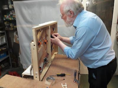
Geoff had redesigned the magnet frame from the previous week and 3D printed 3 in the black PLA. The black produces a much cleaner model, but is harder to inspect, especially in shadowy spaces. One unit was assembled for installation on the engine shed board.


Firstly, space had to be made for the unit as they weren't part of the design when the electrics were first installed. Fortunately, the connector block and loom plug base could be moved down without too much bother. Geoff had undertaken some research on neodymium magnets and discovered that they are produced with (at least) two field configurations. However, ours seem to be the same pattern, so the new unit was fitted. Some alignment adjustments were required to get the best coupler operation, but a working position was achieved. On his 00 layout, Geoff had designed and 3D printed a drilling jig that fitted between the rails and allowed accurate alignment holes to be drilled. He might make one for the two remaining magnets - because he can!


We then moved onto the Masons yard board. First, a connector block was moved from the right hand side, through a pre-prepared hole in the cross-brace and onto to left hand side. 

(Pre brace hacking)

The central brace was then found to be exactly where the magnet needed to go, so after marking the spot, a plunge saw was used to cut the brace. However, the brace fixing screw was also exactly in the magnet position. This time, brute force was used to wrench the screw out.

The existing wiring was then reviewed. The introduction of the servo-driven magnets required additional wires; A) To connect them to the Mega Point Controller (MPC) on the engine shed board and B) to connect to on/off switches on the control panel. The two new magnets on the engine shed could use spare loom wires, but we now needed to connect the two new uncouplers from the Masons board to the MPC as well. 

Configurations of signal wires, switch wires, common ground wires were assessed. The Cinch plug and sockets we had available also had to be taken into account. All of the notes and diagrams from the initial board wiring records were also reviewed. The future use/operation of the spare 'ports' on the MPC (operating doors, cranes etc.) also had to be considered. After considerable deliberation, a plan was decided. A new 12-way socket would be fitted to the engine shed board. All existing and new servo control wires would be wired through this socket, which would free-up connections to the shed board (see later*). There was plenty of spare wiring capacity on the Masons board for the new wiring.


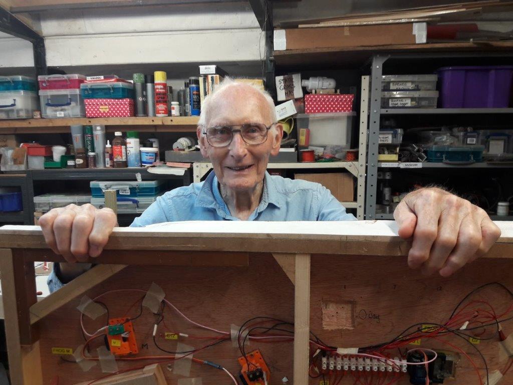
The session was ended at this point as we were both ready for a break!

* The redesign process above also highlighted the 'apparent' lack of consideration of lighting control. On the other boards, a laptop power supply provided 19v DC to each board which was then used for lighting, sound units, accessories etc. The switches for these were located at the back of the layout. However, for the two new boards, there wasn't a single 'back', as they would be reversed in 'Shed' and 'Exhibition' format. Switching could be provided on (under) the boards or on the control panel. The extra wiring capacity makes both options viable. It should also be remembered that in these operational configurations, the control panel needs to be reversed, so 'up/down' switches have to be considered. The current plan is to have a master switch reversing the operations for each arrangement!


Wednesday 20th July 2022

Worklist:
Fit more uncoupling magnets.

A full house again and the temperature had reduced following a scorching start to the week.

The engine shed board was readied for work and a new home for the wiring block that was right in the way of the new magnet mechanism was assessed. It had been thought that the wring would have to be extended, but a new location was found requiring no work, albeit at the limits of the existing wire range. It was soon realised that the router couldn't be used to form the recess in the board this time. It was decided to use a circular saw blade in the Dremel to cut a slot around the area and remove the plywood using a chisel. All went well until Stephen stepped in to finish Geoff's initial work and disaster!!! In a lapse of concentration, the chisel was pushed through the board. It could have passed through cleanly, but instead, a whole section of Peco track was ripped off the base. Rather than leave it for another day, it was decided to repair the track immediately. The rail ends were cut, the damaged section removed and a piece of new track prepared and fitted.

In no time, efforts were concentrated back onto the magnet unit. Geoff had redesigned and 3D printed some more frames that included support for the double magnets on Worton Court. However, a new/cheaper reel of PLA filament had been used that was messier and less stable than the usual material and a lot more cleaning-up was required. (It was chosen because being white, it was easier to study the unit moving under the layout). In fact, a few splits also had to be repaired, but 3 units were eventually assembled. A steel keep-plate was glued onto a new frame, then the magnets, then the central steel spacer added and the unit screwed in place. Unfortunately, it didn't work very well. The unit was re-fixed in a slightly new position without change (we thought the track had moved). The rest of the session was spent trying various arrangements of the magnets, rotating, flipping and swapping the magnets themselves - all to no avail. We had a working uncoupler a few inches away, so what was going on? Although we had achieved a lot, the session ended on a down-beat. We knew the north/south poles of the neodymium magnets were nothing like a traditional magnet, but are they all the same? Geoff will do some research into them for next week. 


The white connector strip was moved downwards out of the way.
The hole being cut with a circular saw in a Dremel.

Ready for the magnet unit. (Working black uncoupler unit).


The track being replaced.


Wednesday 13th July 2022

Worklist:
Start developing the drop-down uncoupling magnet mechanism.

Geoff had been under-the-weather last week and this week, Laurence was sensibly avoiding the extreme heat of the last few days.

Geoff assembled a variety of mechanism elements that he had developed for his 00 layout. These comprise 2no. 3D printed units - one for fixing to the layout and another to house the moveable plate for the neodymium magnet. He had produced numerous variations to suit different situations on the layout. Interestingly, some designs housed the servos on the base, but also had a few on the moving plate. Components for a basic type were selected. The units are designed for a single magnet with steel rod sections atop the flat rectangular magnets, to extend the downward-pull field required for Sprat and Winkle couplings. Our requirement now was for sideways attraction of the Kadee drop-bar provided by two side-by-side magnets. Some experimentation was required.

A rig was assembled to assess the required proximity of the magnet to the track - i.e. how big would the hole in the baseboard need to be? This confirmed a standard hinge was suitable and indicated the sort of packing required. After more experimentation, it appeared that the fields of the current stock of magnets varied from the originals, and a central spacer was now required to obtain maximum sideways throw. 


All components were glued onto a keeper plate and the assembly glued onto the hinge base plate. 


As no thought had been invested in allowing space to locate the magnet units (!), it was decided to fit the engine shed siding magnet first as it was the easiest to fit, requiring (almost) nothing to be moved. The position was marked underneath, a hole routed out (a dedicated ply spacer was made for the router) and the unit screwed in place. Lessons were learnt at every stage!


A plug-in servo tester/adjuster was used to test the installation, and proved it worked and was properly housed. A small square of foam was fixed on the baseboard to obviate 'slap' experienced on the 00 layout.


A bit of hand-shunting proved that we had a working uncoupling magnet. Finally, an assessment was made of the options and work required to move wires and connector strips for the other three units. One for next week.


Whilst dismantling the layout to fit the unit, the end of the 'Quarry tunnel' was visible. Apart from the vertical support on the corner, the tunnel is open at the back for access to track and stock.


Wednesday 29th June 2022

Worklist:
Work out where to locate the magnets on the two 'exhibition' boards.

Un-planned worklist:
Rectify electrical feed problem on points.
Rectify section switch issue in engine shed.

A full house and it was straight into magnet positioning. Track was cleaned, two loco's and some open wagons were placed on the track. We immediately ran into trouble running Laurence's Deceauville 0-6-0 loco as it lurched over the first point. Examination of wheels and gauge proved 'ok', but the problem was a wire on the inside of the point rail near the frog. The combination of 'just ok' wheels and the slightly protruding wire caused the lurching. Geoff explained that the wire was a new design of blade electrical feed, which, when filed down, broke up. New jumper feeds were added to both blades, which will have to be repeated for the other two points.


After some testing, it was decided that the uncoupling magnet on the mainline was best placed in the centre of the straight section of track, to ensure the optimum coupler operation. Likewise, the magnet for the yard siding was similarly positioned. An additional magnet was proposed closer to the point, but this was omitted once all operations had been investigated (see later).


It was decided to make provision for uncoupling a wagon in the engine shed head shunt. Wagons were positioned to identify the fouling point and a magnet confirmed as viable. This is an example of where a retractable magnet is useful as it would be very easy to shunt a slightly too long wagon into the siding and not be able to couple onto it for extraction, as occasionally happens in the Worton Court goods shed.


While investigating dropping off and collecting 2/3 wagons, a magnet near to the engine shed was identified as very useful. This obviated the need for two magnets in the yard siding.


 The final magnet layout:

Whilst running into the engine shed, it was noted that either of the section switches could be used to isolate/power the area. At first, a potentially misplaced shed feed was repositioned without resolving the issue. It was then decided that a rail break could be at fault. After some digging into the plaster floor at the rail break and scraping the copper sleeper, the problem was resolved. Again, despite a few problems, there was positive progress and the session had been enjoyable. 

So far, Geoff's servo operated hinged magnet units on his 00 layout have only needed one magnet pulling downwards. A modification will be needed to facilitate the side-by-side pair needed for the Kadee magnets, which have to pull the droppers sideways. A test rig will be required, which will be started next.

Typical train movements discussed:

Only small locomotives will enter the building and yard beyond. This could be a dedicated company loco, or a pilot located at the engine shed. 

It is assumed that the main delivery to the factory is blocks of stone from the quarry. These could be in the same wagons as the crushed stone, or in 2-plank wagons identified previously. In either case, 2 or 3 wagons could be added to trains coming down from the quarry (6/7 wagon fiddle yard max.). Trains dropping off these wagons will need a pilot to shunt the wagons into the yard and onward to the fiddle yard beyond.

Dedicated trains might also be employed for train’s up to a maximum of 7 open wagons. The real capacity of the mason’s factory has not been determined/fixed so trains may change with operation and use.

Empty wagons would need to be returned to the quarry. These can be brought out of the fiddle yard with a pilot and left in the yard to be added to a train by its loco.

The factory will probably require coal and other materials, which are likely to be supplied directly via the interchange down the line. With the magnets proposed, these wagons can be positioned anywhere in the train and shunted by the delivery loco into the yard. A pilot can then be employed to move the wagons further into the factory and fiddle yard.