Wednesday 22nd December 2021

Worklist:
Scenery shaping
Retaining wall
Cottage designs

It was great to have all three together again and some catching up took place over tea and mince pies.

The first job was to remove board #4 (the scenic exchange board) and replace it with the bridge board so that the foam blocks on the engine shed board could be shaped to suit the bridge hillside. Once the ES board is more advanced, the adjoining boards will be swapped back to allow board #4 to be shaped to match the ES board.

Board #4

Bridge board

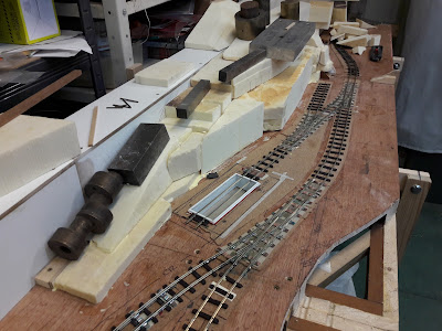
Geoff got to work with a pair of Surform tools - one long and one short - both of which were perfect for the job. 


Edges were shaved off, then the cottage footpath slope was evened out. Debris was then hoovered off and the slopes admired.


Extensive discussions took place on how to treat the front face of the hill adjacent the main line. It was quickly decided that to match the stonework adjacent the quarry siding 'next door', plaster cast rocks will be used. The mould was found, but there was no casting plaster. Unable to use our previous supplier, Stephen will either find another source or bring some one-coat plaster he has been using at home. The foam where it will sit will be left intact until the rocks have been cast.

It was decided that the rest of the hillside - the lower height section - was to have a coursed stone retaining wall. A sheet from the pack purchased for the buildings from Slaters matching the bridge stonework, was offered-up and agreed. A length of 5mm plywood was cut to shape and the plasticard stonework glued on with contact adhesive. The area of foam down the back of the engine shed was trimmed to allow a reasonable 'maintenance gap'. Strips of wood were then glued onto the back of the plywood to allow a row of coping stones to be fitted on top, in due course.

One thing we noticed was missing stonework on the rear of the bridge, facing the fiddleyard. This, and a rather poor lining to the bridge portal itself will need to be made good.

While this was going on, Stephen presented some rough sketches he'd prepared of the cottage elevations. He had become particularly concerned about the way the doors worked with the steep slope which was now appearing. The pairs of cottages had been drawn with two options:  A - central doors, which worked with the slope, but the floor levels were either well below ground or well above it, which might look slightly odd. B - having the doors wide apart created the need for large steps outside the lower doors, which again looked impractical and ate into minimal footpath space. C - the previously undrawn third option was to have stepped single cottages, which Stephen now preferred, but this was not universally accepted! (D - sloping roofs, was common in such workers accommodation, but was not an attractive solution). 


Stephen first used his paper models to demonstrate the perceived problem, then, after cutting them in half, showed how much better the single cottages option worked. The group were swayed over and Geoff printed off some more cottages onto thin card, to get a proper view of the whole terrace. It looked even better. Even bending the cottages outwards onto the newly created hilltop worked well for single units, which we had discussed early on, but the double cottages never really fitted. 

Everyone was pleased at how well it all worked. We discussed the construction of the 'winding' top two cottages and foresaw no problems - just interesting details!


The coursed stone retaining wall.


Another cut-and-paste exercise was for a slightly larger dwelling at yard level - a house for the yard manager? Double fronted and with a full height first floor to lift it above the tunnel structure behind. Maybe in 1963, it has become an office? 


Geoff was also keen for there to be a discernible gap between this house and the adjacent industrial building which, presently, will be a corrugated iron infill unit. Various ideas were discussed, but the presence of the constructed buildings will help to decide the answer.


Wednesday 15th December 2021

Worklist:
Check rails for yard road surface retension.
Engine shed pit edging.
Scenery sub-structure.

Laurence on family duties this week.

Geoff finished off the check rails in the mason's yard to contain the road surfaces and only had a few short sections of the 'repurposed' rail left over. It looked great.


Stephen used prepared strips of 2mm plastikard to reinforce the edges of the engine shed pit. 


Attention then turned to the foam blocks that will eventually become the sub-structure of the hills. Pieces cut up and shaped during the previous exercise and dismantled to work on the underside of the layout were slowly repositioned. Anything that looked ok was glued down with PVA glue. The bandsaw made quick and clean work of shaping some pieces.


We had to stop when the numerous lumps of metal to hold the foam down got in the way. There's always next week.


The paper building models were loosely placed on the foam structure and generally worked well, especially on the section extending out to the engine shed siding where the cottages and winding footpath could now be envisaged much better.
 

Wednesday 8th December 2021

Worklist:
Refit engine shed point servo, point actuator and section wiring.

Just Laurence and Geoff as Stephen not too well, but there was no slacking. The layout was cleared of loose items and the boards clamped vertically to give easy access underneath. The realignment of the engine shed road meant moving the point and so refitting the servo meant a new hole for the activation wire. Once complete, the point, new track section and the inspection pit rails were all satisfactorily tested.


Worklist:
Continue on from last week.....

Well, that was the plan, but Stephen had taken one of Geoff's books on railways in quarries home the previous week and had found a photo that inspired him on two fronts.


Firstly, the projecting corrugated iron clad building could be incorporated into the scene, straddling the track as it enters the masons main building? Secondly, the roadway with check rails and lorries, was exactly as envisaged for the masons yard. 

Due to car problems, Laurence was a little late, so he found Geoff and Stephen deep into a discussion about how to recreate the scene. Working around the Peco plastic sleepers and oversized spikes was the issue. Thin plastic strip - flimsy and fiddly. Code 100 upright - trial notches were cut in the base of a short strip to avoid the spikes, but it became higher than the track rails due to wood-grain. This was to be avoided as it could prevent cleaning of the running rails or if level, whilst the running rails needed to be clean, the check rails really needed to be dirty - a height difference was needed. Code 100 on its side soldered to paxolin sleepers - nope. Code 70 flat-bottom - too fine. We needed chunky flat-bottom rail just under code 100. Geoff started rummaging and found the box he wanted. It was the remains of a large quantity of track sections with plastic ballast bases, bought for 50p. We were aware of code 83 rail, but this was 89/90 thou high. It was perfect, but there wasn't much and it was in lengths of 50-200mm. It was all stripped from the bases and the bottoms cleaned, ready for soldering. Geoff marked the sleeper spike positions and ground a section of the rail away to suit. Paxolin sleepers were packed in alternate gaps and the check rain soldered in place. It looked great.


We also discussed the guarding of the crossing, yard and roadways. Geoff was able to describe the probable requirements - no crossing gates, minimal yard enclosure/fencing etc. The area could be maintained fairly open, which was ideal.

Stephen drifted over to the engine shed and, after forming the section break at the doorway, fixed the rails spanning the inspection pit. A quick check in the control panel and under-board wiring strip confirmed the electrical connection to the shed section had still to be fitted, which it was.


The rails are stiff enough to support a model train, so would be operational for running sessions. Edgings, columns, bracing etc will be fitted in due course.

A long discussion ensued regarding the cottages. Stephen was concerned about the size of the paper mock-ups he'd produced previously in comparison to the industrial buildings. He'd drawn-up a new cottage from the booklet - 'Welsh Industrial Workers Housing 1775-1875'. This was smaller, with smaller windows, and the reduced details made the appearance much better. Q - were we looking at the front or rear of the cottages? The space between the engine shed and cottages was restricted, maybe not suitable for front doors? Furthermore, the path would be minimal, and would end up down in the stone yard. Geoff was adamant that the buildings drawn, although 'Fronts', were similar to the backs of some he'd seen alongside a North Wales NG railway line (with the addition of some kitchen plumbing!). Regarding the path, he explained that it would be quite normal for such a path to meander through a railway yard. The bottom dwelling could even be a larger managers house. It all sounded feasible.


Wednesday 17th November 2021

Worklist:
Develop the scenery sub-structure.
Inspection pit and trackwork.
Review stonework sheets.

No Laurence this week as he was taking it easy. The clamps were taken off the profile boards and their support frames, and everything that should have been solidly glued together was. There was a general clean-up and then Geoff decided to complete the trackwork into the engine shed and start the lining of the pit. Thick grey card was glued on the floor of the pit. English bond plastikard brickwork was laminated with some thicker plain sheet for rigidity and glued onto the sides. 2mm thick plastic strips were prepared ready to be glued along the top edge of the upstands to provide a stop for the plaster. Support steels and posts to follow.


Meanwhile, Stephen accumulated offcuts of insulation board and started cutting into smaller sections, then notching and trimming as required to fit them into the various spaces. This triggered some discussion about hillside shapes and heights, and the cuttings for the tracks. This design stage will go on for a while as we work out what actually works and what makes for an interesting backdrop.


Stephen had purchased sheets of Slaters dressed stone and coursed stone. The dressed stone is as the bridge sides and will be used on the industrial buildings while the flatter, coursed stone looks ideal for the dwellings. With the dressed stone held up over the large cardboard building, it definitely looked impressive and might sway us back to using for the main building in lieu of the corrugated iron. The iron will still be used on one or more of the other buildings as it is very typical of stone mason premises and will be fun/interesting to use.


Wednesday 10th November 2021

Worklist:
Fit scenery profile onto adapter board #4.
Investigate rest of scenery on adapter board #4.
Review outstanding engine shed trackwork.
Review building finishes generally.

A full house and the first job was to confirm the first profile board had glued satisfactorily. The bridge board was removed and replaced with the empty adapter board #4. Blocks of wood were prepared and the profile boards glued and clamped into place. The small profile unit at the front of the layout and a preliminary backscene board were also added.


This prompted a discussion about how to finish off board #4 as it connects to board #3. Although not an exhibition board, #4 will have scenery, for our own pleasure. Board #3 (1 of two exchange boards) will be plain black. This discussion became more animated than expected. Stephen and Geoff agreed on the ground tapering down to track level rather than extending at a fixed height. Stephen promoted a 'stage effect', with a rising hillside slowly going over the track creating the effect of the track going off at an angle. Geoff preferred a 'practical' solution with a tunnel mouth, but trying to create a similar effect. Geoff produced an MDF tunnel mouth and various trials with strips of wood and cardboard took place. As a compromise, the tunnel mouth was widened to allow it to be placed at an un-prototypical angle, in order to point away from the actual track route - Geoff glued it down quickly. We'll see what it looks like next week when we can develop the ground levels more easily.


The only outstanding section of track is the engine shed and inspection pit. A discussion took place on materials and order of installation: concrete floor (cardboard), brickwork side walls (a piece of Slaters English bond was found), lay track, plastic beam sections to be glued to underside of rails (steels found), intermediate rail/beam support posts (2 no. each rail), plastic tie bars between rails (through holes drilled in rails - to maintain gauge), concrete floor up to rail top (plaster). The enclosing building has yet to be designed, but that will be part of the whole building design exercise for the mason's yard board, which was briefly discussed. The extent of the corrugated has not been decided, but Slaters dressed stone for the works/factory buildings was agreed, with Slaters more random 'stone courses' for the houses. 

With everything glued up solidly, we hope to start investigating the main ground profiles using insulation board. Exciting stuff!


Wednesday 3rd November 2021

Worklist:
Complete realignment of engine shed point and siding.
Fit engine shed board joint end profile.
Review modified corrugated iron sheet machine.

A full house and finishing the point realignment was the first job. Geoff made short work of the exercise. Stephen knocked-up a cardboard shed building to get the feel of the space.


A good while was spent assessing the fixing of the shed board tunnel unit, which actually led to the scenery profile board being fixed in place with wood blocks and the tunnel left removeable, for the time being. Next week, the shape of the scenery on that board can be assessed and the mirror of the profile board will be fitted to Adapter Board #4.


Geoff had scaled down the corrugated iron rolling machine he'd downloaded (approx. 40%) and modified it to accommodate 8ft long sheets. However, the narrower and longer rollers deflected slightly in the middle which meant the corrugations were shallower or non-existent. When manually forced through, the sheets were very good, so the rollers will be reinforced and mounted in a stronger frame.


The last minutes of the session were spent looking over the paper buildings in the mason's yard and along the tunnel/backdrop. Nothing has been agreed yet so there's still a lot of experimentation required, but it should be a bit easier now the area surrounds are becoming 'firmed up'. 


Wednesday 27th October 2021

Worklist:
Review new paper building.
Realign engine shed point.
Make bridge board scenery profiles.
Discuss engine shed siding ash pit.
Discuss engine shed design including work pit.
Review corrugated iron 'machine'.

Laurence was taking it easy today so just the other two.

Stephen's new paper building was dropped into place. The corrugated store with a loading dock worked well, although both agreed that incorporating a ridge across the roof would allow the odd triangular back-half to disappear.


The space next to it would fill the gap to the board end. The idea of a stone building was developed with an industrial ground floor with large access door, possibly windows, but with the backs of houses above. This combining of houses and industrial use had often figured in books relating to workman's housing. Stephen will create something for discussion.

Geoff then moved onto realigning the engine shed point as agreed the previous week. This meant moving the point back about 20mm and closer to the main line. Much experimentation was needed, including the introduction of a 3D printed Deceauville loco body and the 'engine shed box', before the final position was agreed.


Factors to be considered included the proximity of the building corner to the mason's yard siding (rather than the main line). It was mooted that if it was found to be too tight, it would be a nice feature to chamfer the building corner. Space for a loco to 'stand' in front of the shed doors to run forward to the siding was also needed. The final position was agreed.


The dimensions and layout of the shed were also considered, which included the inspection pit. So much thought went into it, that it made sense to build the pit next.


Steel sizes, step access, working space, wall thickness etc all became lines and dimensions on the board.


The drill came out for the corner holes, the jig-saw cut the floor out, timber strip was glued and screwed underneath to form the pit and a small panel of plywood created the pit floor. Some plastic steel sections were also found for the rail supports.


Meanwhile, Stephen had produced two MDF cut-outs of the bridge board ground profile. One will go onto the engine shed board to marry up with the bridge board face for the 6-board exhibition format. The other will be used on adapter board #4 for use in the workshop.

Finally, Geoff had found a free, corrugated iron machine 3D design and files on 'Thingiverse' and printed a set of components out. He'd also sourced some 0.1mm aluminium and copper sheet. A small piece of aluminium was manually fed through the 'teeth' and a superb piece of corrugated iron appeared. Although described as 'O' scale, it appears oversized, so Geoff is going to experiment with rescaling the components and try printing it again.


A wonderfully productive day!