Thursday 23rd October

Worklist:
Develop the scenery around the mine entrance, including the bridge and roadway.

In Laurence's absence, Geoff and Stephen made a right mess of the workshop, but it was great fun.

Backboard - the first job was to cut the backboard down to reflect the future ground and road outline.

Archway - the card tunnel mouth was twice-transferred to an offcut of 9mm MDF and then both cut out, glued together and held with clips to set. The end next to the siding was later cut back to allow the 'rocks' to get past.


Bridge & roadway - thick modelling card was chosen for the road bed. The side walls were marked 'brass-rubbing' style onto newspaper (all we had to hand). These were taped to thick grey card and cut out using the band-saw!


The top of the road posed an interesting problem. As previously alluded to, the cut through the road at an acute angle generates a steep cross fall which just doesn't look right, so wedges were cut to level the road up to make it look right (we hope). The card was glued together (not to the subframe yet) and left to dry.


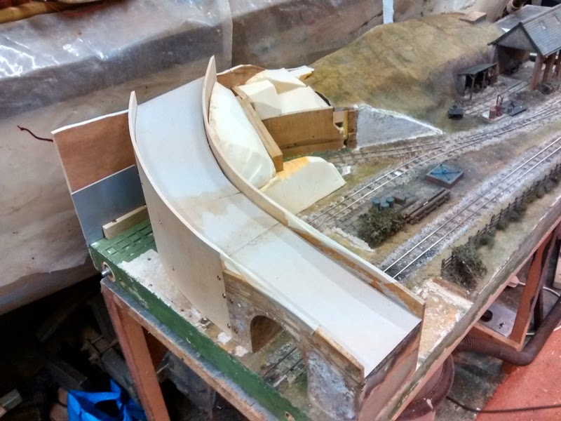
We had a straight piece of ply already cut out for the extension of the tunnel entrance back wall, but it was too close for a decent clearance 'post-facing material application'. A few cuts in the back generated a nice curve and it was glued into place. The old plaster 'stonework' was taken off (only held in place by the paint) and we spent quite a while discussing ideas for the retaining wall face treatment. We're now favouring a sleeper wall with bullhead rail spreaders, held back with ground anchors and big nuts. ExpoNG at Swanley is imminent, so some detailing parts will be sought.


We then turned our attention to the rock faces. The newspaper balls were discarded in favour of foam blocks. Geoff had rescued (with permission) a few pieces of insulation board from a local skip. He then spent quite a while on the band-saw, carving and shaping pieces to form a base for a Modroc overlay.


At the same time, Stephen worked on a piece of thin ply, adjusting it to fit into the back of the tunnel and hide the main structure. It won't be visible from most angles, especially after it's painted black/grey.


We decided that the bridge side walls would stop once securely based on the rock substrate. The wall on the outside of the curve can be continued as a dry stone wall and provide a backdrop. As highlighted earlier, the inner wall just goes up too high, so the red area will be removed in due course, and a fence fitted instead (see previous week sketch). 


We were covered in sawdust, foam dust and there were slivers of ply and foam everywhere, but we felt we'd moved things along in the right direction. Meeting will be patchy for a few weeks, but we'll have plenty to think about.


Thursday 16th October

Worklist:
Develop the bridge/mine entrance/sidings area a bit more
Play trains
Finish the central board joint pin assembly.

Stephen & Geoff got the bridge board out and reviewed Geoff's work reinforcing the back of the bridge/rod structure - an excellent job. Geoff had come to the conclusion that having a cutting on the outside of the roadway wasn't practical after all.

A hill profile was sketched on the backboard and a scrap of ply was shaped and inserted between the backboard support fin and the existing front wall. The void was filled with crumpled newspaper to get a feel of the resulting landscape - it looked good.

(When firmly compacted, the newspaper balls will form a good, light-weight sub-base for the Modroc plaster covering that we will apply to form the hill surfaces.)

A piece of grey card was marked with a tunnel mouth - first, the same size as the main line, but then reduced a bit - more befitting for a mine. How to fit the mouth/arch into the scenario we had created was not an easy job, but when Geoff struck a diagonal line across over the top of the arch, it suddenly looked right. A few cuts, scores and folds, and we had our mine entrance.  More balls of paper filled-in another void and allowed the rest of the rock/wall interfaces to be assessed/discussed. The sloping coping made all the difference - a dynamic transition from low-to-high. We had an attractive, realistic solution!


How the road and its side walls joined the backboard was discussed. The difference in wall height still looked a bit odd, but could be overcome by cutting the inner wall back and fitting a fence or hedge in its place, as the early sketches for the area - further development required. Whether the backboard is cut down to the proposed road level, or the road height increased would also be resolved by experimentation. The steepness of the road still looks exciting.


The first train to run up the mine line and into the fiddle yard was a log train. Using the main station yard as a mustering area for supply trains to the mine has become an interesting addition to the running roster. The siding is designated as Worton Minerals property and the longer mine adit line provides excellent scope for shunting. We'll fit the sign back into a suitable location, in due course.


We were adamant that this week would be primarily a 'playing trains' day, so after lunch, all of the boards were assembled, not forgetting to screw the washers of the reformed alignment pins into place. S&L had both brought additional stock, some of which hadn't turned a wheel for a decade or more. It was wonderful to shunt a bit of stock around familiarising ourselves with points, magnets, routes, and also finding dirty track spots, dodgy track etc.


Something none of us had done before was work with cassettes in a fiddle yard. We've seen different methods used at shows and can now see the reason for them. We'll have to develop our own way of working, as we go along.


PS: The central alignment pins worked perfectly.

Thursday 9th October

Worklist:
Separate the two centre boards that had been worked on last week and check that the pin realignment had worked.
Continue painting track.
Assess and design the new bridge and mine entrance.

Geoff started off with a block and fine emery paper, cleaning the track he'd painted last week. He then got the Dremel out, with a small grinding disk, and ground down areas of old solder that showed up when the painted track was cleaned. This usually occurred where wires had been soldered too high up the rail edge. He then touched up the track edges - a really nice job that made it all look very neat.

Stephen tackled the bridge/mine entrance redesign. Following posting the various real mine entrance photos last week, the consensus was a combination of 3 and 1 should be investigated. A rough sketch was prepared.


Having decided to use the old bridge as a base, it was clamped in place. Only the front section would be used, so picturing the new road beyond the brow of the bridge needed a visual aid. Enter - a length of old draught excluder, a length of bendy ply and a cardboard cut-out of a mine entrance.....


The exercise allowed us to play with the steepness of the road, which looked quite exciting.

Taking the bull by the horns, the bridge was cut down to the essential section and screwed into place. Ply strips were glued inside the end section to allow the sides to be extended, flush with the existing. 


Several sections of roof batten and plywood were cut up for spacers and fixing strips. We press-ganged Laurence into action, as we like to keep him busy!


A piece of flexible plywood was coaxed into position, then curved and nudged and curved and prodded, and then fettled until a reasonable shape was achieved. A clearance hole was cut out for the track, although the actual tunnel mouth will be further forward. A plank was clamped in place to hold it in the desired position. Then blocks and spacers were glued and screwed to the inner wall.


Then the outer wall was cut to the same profile and fixed to the other side. But then 'Geometry' raised it's head. Because the outer wall is cut shorter, the road at that point is technically much lower down the slope and so the road and parapet should be much lower, which might look very odd, so we'll have to look at it in detail, next week. 

The bridge will span across the track and into the mass of rock beyond (where the mine entrance is cut through). The bridge parapets will then become fences or dry stone walls up into the hills beyond.The area where the mine track goes into the fiddle yard will be kept open. The idea is to treat it as a cutting, and have trees simulating being down in the cutting, with their canopies just getting up to wall height. Again, we'll have to see how that looks.


From the front, we think it looks very promising. The side wall of the old entrance will be extended up to the new entrance, which will be forward of the plywood cut-out. This will enable a sloping rock mass to be formed between the entrance and the roadside wall. The resulting road looked every bit as exciting as the mock-up suggested, if not more!


None of us could believe the progress we made on the bridge/roadway/mine entrance today. Another satisfying session.

Geoff will fit some ply back boards to secure the ends of the curved plywood sides, which will enable us to get on with the other panels and features next week. The tunnel mouth will be the difficult job; trying to make the transition look realistic.


The final task of the day was to take the two boards apart and check the pin realignment, which looked like it had worked OK. We'll test it out next week.

Thursday 2nd October

Worklist:
Check last weeks board alignment exercise.
Discussion on scenery
Track - paint rails, infill magnet holes

The session started badly. We reassembled the two middle boards that we had painstakingly reformed the locator pins on the previous week. The track alignment was appalling. We were dumbfounded!

Unwilling to take the pin assemblies apart knowing the damage it could cause, the only answer was to take the washers off the other board and re-fix them in better positions. The washers were just screwed, so came off easily. The alignment pin and board bolt holes were carefully examined. It appeared that there wasn't sufficient clearance around one of them to allow the boards to be bolted up in line, and so a degree of distortion was occurring. The holes were opened up to rectify the problem. The washers now had to be refitted to the board interface, but in their new, slightly adjusted positions and screw holes. To achieve this, circles of thin foam were placed over the pins, and slow-set Araldite dabs applied to the washers. The holes in the washers were rotated 60 degrees to previously and the boards were reassembled. Hopefully, the foam should push the washers against the boards. Next week, the boards can be separated and the screws fitted to hold the washers firmly. Time will tell.

With the boards laid flat on the bench, with heavy steel strips clamped to the sides, all we could do was scenic and track work. We all gravitated to a task - Laurence worked on filling the old magnet holes with dummy sleepers and planks.


Geoff got comfortable and started painting the new trackwork brown-ish and any rails within reach, a dirty rust colour.


Stephen set-to cutting a bit more of the hillside out, to make it easier to form the new, higher hill. Then he started to mock-up the new bridge, but what should the loading gauge for the underpass be? Getting out the old bridge as a template, he realised that as all of our stock would have gone under it at some time, it would form the perfect base for the new bridge, but it would have to be cleaned up.


After much scraping and filing, the bridge was free from crumbling Pyruma and splintering stripwood. Geoff proffered some 3mm MDF sheet and the new bridge construction fell into place. A layer of the MDF on the outsides, shaped to a new profile, with 5mm Polyboard (or ply) sitting inside it, on top of the existing ply sides. The new sides will also cover the old, small tunnel. The Polyboard strip gives an idea of what the new road/path up into the hills might be.


Looking at the new arrangement of the now 'open' line going off to the mine, Geoff suggested moving the tunnel mouth further back into the hillside. This would allow the adit to be less prominent and more easily modelled, and allow the open section to be used for shunting, for the adjacent siding. No count needed - unanimously carried. (Geoff - we'll need another magnet!)

A wonderful end to what could have been a very disappointing session.


A few ideas for mine entrances.
The first two look very promising.