Wednesday 30th October

Worklist:
Lay more track.
Transfer accurate rail setting out from bridge board.

Laurence on an autumn break, so just two this week. Geoff had been doing lots of sawing in the workshop in the week, so Stephen did a bit of housekeeping before track-laying recommenced. Geoff had made the three remaining points and just needed to finish the tie bars.


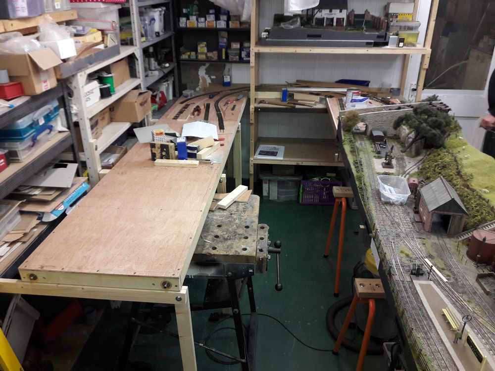
It was decided to work on board #5, the engine shed, and it made sense to move it into its exhibition position next to the bridge, in order to get the accurate rail setting-out. Cork underlay was glued down and brass screws inserted at the board edge.


The first point was offered-up and once its position was confirmed and rail-ends trimmed, a hole for the point actuator wire was drilled and the point fixed down. We have been using Peco track pins (small head) on scenic trackwork, with the heads close to the rail on homemade track.


While Geoff continued with the next point, Stephen fitted screws for the hidden line connection with the bridge board and then laid track down to the next board joint.


When the second point had been fitted, board #5 was disconnected and all boards reassembled in their workshop format. The track ends of board #5 could then be joined to the adaptor board #4. On the tighter inner, reverse curve, a short straight section was soldered at the joint first, then curved back to the existing piece of track joining with an unsoldered, fishplated joint.


While the boards were separated, the tee nuts were also fitted to the remainder of the board connections.


While board #5 was attached to the bridge board, it was possible to assess the physical relationship of the hillside profile at the bridge and the small siding off the engine shed.  The siding is very short and its primary purpose is more of a catch-point, but is sufficient for a small loco. A retaining wall will no doubt need to be employed. There's probably a bit more of the Slaters walling in a box somewhere.


Stephen had been investigating the method of sharing the electrical sections on boards #2 & #3 (small end boards), which were to be the train exchange area. The replication of two-way 'hall/stair lighting' had intrigued him and a small test rig had been made up. It used a DPDT relay for switching the track power and another, in parallel, for indicator lights. Illuminated latching push button switches would replace the loose slide switches and led's.


One of these units would be required for each track creating two switch boxes, each with two push buttons. The position of the switch boxes was not immediately obvious, so long leads could be used to try out different locations. Alternatively, WIFI or IR control could be investigated, all proving that it was not a simple matter to resolve. It all highlights that fact that the full wiring and operational implications of the workshop/exhibition layout setups need to be resolved as son as possible.

One aspect of the electrics that has probably been resolved since the previous week occurred when Stephen found a new source of the Cinch range of plugs and sockets. These were successfully used on the Cottesmore layout previously made/supplied by RS Components, but had been discontinued. Mouser UK now have all four pin options available https://www.mouser.co.uk/new/dura-con/dura-con-j-type-connectors/


Wednesday 23rd October

Worklist:
Continue with support legs
Continue with track laying

In other words, more of the same... again.

After getting the boards level on temporary supports, Geoff and Laurence fitted bracket number 2, which supports the end of extension board #5, the engine shed board.


They moved straight on to the next leg, which needed a slightly different arrangement as the uprights of the racking were just beyond the limit of the next board edge. The final design had the frame clips mounted on the side of the racking upright.


Meanwhile, Stephen pressed on laying track on adaptor board #3. Although the brass screws had arrived, the acute angle of the rails across the board joint meant that solid Paxolin strips made for a much more stable assembly. Geoff made the strips up and Stephen fitted them. Standard track was laid around the outer, quarry tunnel line and modified sleeper track laid along the inner scenic section.


The track onto the next board (Extension #5) cannot be completed as that board now needs to be bolted onto the bridge board to set the exact rail positions (for when they are in the extended exhibition format). Once the rail ends are established, the track can be completed on the board.

Finally, the line of the two runs of boards was checked following the hinge packer insertion last week and all were pleased to see the gap was millimetre perfect.


The final extension board in place (Stone masons). The fiddleyard bolts onto the end with it's other end supported on the spare trestle leg unit. Although quite narrow, we were happy with the space between the board runs operationally and also with the view of the new boards from the operating position on the main station.


Wednesday 16th October

Worklist:
Construct next demountable board leg.
Transfer track layout to next board.
Correct board alignment.
Continue laying track.

Essentially, more of the same this week, so Laurence started to make the next board leg unit.


Whilst board #5 was temporarily supported, Stephen took the opportunity to transfer the track setting out information from Geoff's drawings to the board, ready for the cork underlay to be fitted. This is the first of the new exhibition boards and the exercise enabled discussions on the engine shed area in more detail, including extending the scenery beyond the bridge.

With boards #4 and #5 in place, it was possible to check the alignment with the main station boards and a small 'convergence' was noted. This was corrected by unscrewing one of the hinge-connectors between boards #3 and #4 and inserting some card packers, which subtly changed the board angle.

Geoff and Stephen then continued to lay track on the adaptor boards. Where brass screws had previously been fitted, rail was soldered down at the junctions and the joints cut with a razor saw.


We'd used up our small brass screws the previous week, but the replacement order had failed to arrive, so the joint between the two non-scenic boards was fitted with PCB strips, laminated with card to make up the height and screwed to the baseboard. Finally, the rails were also cut with a razor saw. Out-of-the-box Peco track was used on the non-scenic boards.


Even with all three working in a confined space, we managed to work quite well although we did create quite a mess!


In response to a plea for clarity regarding the boards, names and uses, the following diagram has been produced. There are 6 new boards. Boards 5 and 6 will form a fully scenic, straight-line extension to the existing three-board + fiddleyard layout. In the workshop, the fiddleyard, and boards 5 & 6 will be arranged along the racking wall. The four Adaptor boards (boards 1 - 4) are solely for use in the workshop to join-up the two rows of boards and will not feature in any exhibition format. However, two of these boards (1 & 4) will receive full scenic treatment (and continue to hide the 'quarry' line track). Board 1 also has an engine shed, mimicking that on board 5, to enhance operational interest in the workshop.


Wednesday 9th October

Worklist:
Demountable leg supports.
Point installation.
Point actuator.
Cork underlay.
Track laying.
Electrics.

Another busy and, at times, 'tense' session as we pressed on with several jobs simultaneously. Laurence continued with the initial demountable leg for the layout supports along the racking. The end blocks were glued in placed and when dry, the panel mount plates were fitted to the racking plate and cross-bar end. Stephen had purchased M8 coach bolts and wing nuts for the joint, which when assembled, allowed a successful test to take place. After checking for levels, the first board was successfully bolted in place. Laurence moved on to the next leg.


Geoff worked on the Y point into the engine shed on adaptor board#1 and trimmed the rails to the correct length, before soldering onto the brass screws.


A large DPDT slide switch was to be used for the mechanical movement of the point blades and the frog electrical switching. Some stiff steel wire was sourced for the rod together with some brass tube for its guide/protector. Whilst an in-line spring was considered at one point, a simple omega loop was finally settled-on for the tensioning/adjustment. Everything was prepared, assembled and satisfactorily tested. (The scenery/hill abutting the bridge will extend over the rodding close to the point).


Apart from flitting between and helping the others, Stephen was cutting and gluing down lengths of cork underlay. With the point fitted, the track on adaptor board#1 was completed using Peco track with the sleepers re-spaced, together with all board joint soldered connections.


The day had started with a discussion about electrical connections, distribution and the break-down of control etc. During the lunch break, we had intended to discuss this further, but when Geoff flourished a copy of BRM with a small article on a layout using computer motherboard power supply extension cables, that became the Google/eBay focus of attention. On Cottesmore, we had used an excellent range of robust connectors by RS, but these are no longer available and nothing similar seems to be available. We had used some 'green connectors' (we forget the name) to supplement loom connections, but had to make them up into fly leads. The ATX power cables looked similar in construction and size, and needed no adaptation, and were therefore quite promising.


We'd probably use 50cm extension leads and, as proposed in the article, cut them in half, connecting the loose ends into connector blocks on the layout. They appear to be crimped pins, which we can deal with. More research is required, but an overhaul of the existing loom might be on the cards'.


Wednesday 2nd October

Worklist:
Review latest layout drawings.
Discuss electrical control principles.
Review steel angle shelf reinforcement.
Level and secure shelf unit.
Progress new board legs.
Review new point.
Assess point operation.
Start track laying!

Stephen had produced two new layout drawings showing a) the three possible configurations of the layout in the workshop and b) the layout in its future extended exhibition format. These were to enable the layouts to be discussed more easily in general, but they soon generated a discussion about the electrical operation of the layout in Workshop and future Exhibition format.


Too complicated (and boring) to relate in full, the results were as follows:

The masons/engine shed boards would have a local panel for loco and pointwork control. This would be reversible so that it could be located behind the layout at exhibitions. In exhibition format, the local panel would be able to switch track control to the main station panel to allow it to run through trains, together with loco's going to and from the shed and deliveries to and from the masons yard. An existing section of the main station would be controlled by the local panel to allow full access to the engine shed. Pointwork control would remain under local control as would close shunting of full/empty wagons.


The 'hand-over' between main and local control panels in the workshop would be via a section comprising the two non-scenic adaptor boards (#2 & #3) on the shelf unit. A manual switch on the board will decide which panel has control. The local panel will be able to cede control to the main panel for full-length runs.


We then reviewed the excellent job Geoff had made in fitting a length of steel angle under the front support rail of the shelf unit. This takes a lot of the weight of the first board in operating mode and had sagged a bit.


The whole unit was then checked for level, which entailed some unscrewing, packing and refixing, but was essential for the setting-up of new boards. Once levelled, a new bracket for the overhanging adaptor board was fitted.


Laurence made up and fitted a timber plate for the first leg bracket and a datum was transferred onto the plate. He then started to construct the first leg support unit.


The opportunity was also taken to infill the large hole in adaptor board #3 around the shelf unit post, to fully support the cork underlay and track.


Geoff had completed the Y point for adaptor board #1. The final position will be decided in due course. Rather than fit an electric point motor, a simple rigid wire link rod from a SPDT slide switch will be used, located near the back of the board. The switch is required for frog switching and provides a solid throw.


Geoff and Stephen then started cutting the ties between the sleepers of two lengths of Peco 0-16.5 flexitrack (they can become visible and unsightly if ballast is too low).


Geoff then fitted brass countersunk screws (nice big flat head) at the board joints and soldered the first section of track in place, which looked really good.


A jig was made and the sleepers were spaced out at 18mm, as agreed the previous week.


Is that the tunnel track?


Another very satisfactory days work.