Wednesday 22nd January 2020

Worklist:
3D printing - pallets.
Discuss wiring investigations.

Laurence was a bit under-the-weather and sensibly chose to stay at home.

The possibility of making some pallets for the mason's yard had appealed to Stephen, who had researched and then produced a drawing, for Geoff to test on his relatively unused 3D printer. The pallet was drawn upside-down, with the bottom stringers omitted to enable the plastic to be built-up off the printer bed without temporary supports. Stringers will be glued on once the pallet has been cleaned up and the 'inside' painted.


Over our first cuppa, Geoff got to grips with the printer that had been set up in the dining room. Still new to the process, several printing options were tried and adjusted until something vaguely recognisable was achieved without too much mess.


The first two 'usable' pallets printed one at a time. The loose sprues of plastic need removing, but they were very pleasing.


More adjusting and testing produced something usable and finally, a production run was completed. One panel failed to adhere to the base and a piece of card was taped in place to allow successive layers of molten plastic to be laid down without spreading onto the adjacent panels. We decided it was a plywood faced pallet that would definitely find its way onto the layout.


A set of ten printed in one go, including the 'plywood - rescue' pallet. They'll fill up lots of corners of the yard, with minimum work from us.


Being a stone masons yard, the main product would be carved stonework. An online search for free 3D drawing files resulted in nothing suitable, so a mixture of funereal and construction products will have to be researched and created 'in-house'. Another feature high on the wish list was a lifting frame and a search produced a very attractive example.


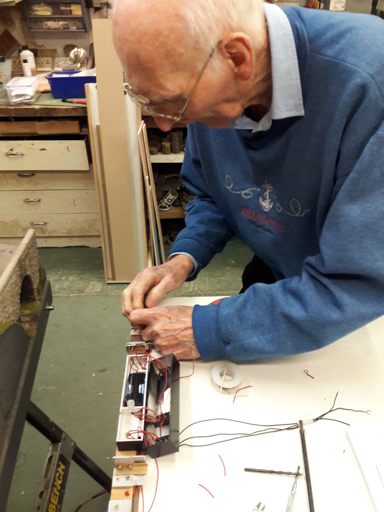
That was the morning used up. After lunch the warmth of the dining room seemed the perfect place to run through Stephen's investigations on the future wiring requirements. It was agreed that a survey of the existing panel wiring, plugs and sockets was required as well as assumed connections for the new Local control panel and loom. Board, track and connection sketches were laid out and checked against spreadsheet pages of panel, plug and socket references that will form the basis of the survey. The main issues were the different configuration of boards using the same looms and connections across board joints, but the schedules stood the investigation. The survey is next, then the purchase of new Cinch plugs and sockets, wiring modifications and ultimately, a new control panel and loom.


Wednesday 15th January 2020

Worklist:
Continue to investigate wiring for fiddleyard and extension boards.

Laurence immediately reminded the group that a running session had been mooted the previous week and had brought stock. As having the boards up and the loom installed would aid the wiring investigations, the three main boards were erected on their trestles. This was useful, as they hadn't been adjusted since the Burton show, when they'd been levelled to suit the timber floor there.

The transitions boards were then added, but the junction between boards #3 and #4 wouldn't go together properly. The joint is not fully on the shelf unit and has more flexibility than desired. To cut a long story short, the rest of the day was spent investigating the problem that entailed filing one of the board location pins, then packing some of the hinge joiners and finally removing the hinge joiners and drilling holes for the standard M8 bolts.

It was all a bit disappointing, but we finally had a solid connection. The two hinge joints sitting on the shelving unit are much more stable and will not be replaced for the time being, so someone will still be required to squeeze in there; well done Stephen!


Hopefully, back to productive work next week.


Wednesday 8th January 2020

Worklist:
Continue installing new cassette road switch unit.
Continue to build new point actuators.

Back to full strength, although Laurence still bore evidence of his fight with the patio doors. At first he took on a monitoring role as he watched Geoff continue to assemble the new point actuators, but he was soon pressed into assisting Stephen wiring-up the fiddleyard cassette power switch unit.

First, the three track feeds were identified and wired into the appropriate switch. Tails with loops on the end were then run-out to the appropriate track connector and bolted in place.


As we adjourned for lunch, Geoff reported that apart from fitting some microswitches, his morning had achieved very little. Unfortunately, every one of his spare servo units had failed as he attempted to convert them to non-radio-control operation, but each in a different way. Motors and/or gearboxes simply didn't work or worked intermittently and all had to be consigned to the bin. It was noted that they were all 'variants' of the original SG90 servos bought for the layout. More of those originals will have to be sourced in due course.

After lunch, the common return tails were connected up on the track switch unit and the assembly was tested. The loose wires will be tidied up once a fully operational test has been completed.

The Bridge board was then joined up to ensure that the switches worked satisfactorily. This is the standard exhibition format, which is essential for the forthcoming exhibition. The new connection for the stonemasons yard can be seen in the centre of the fiddleyard board. In the long workshop format, adaptor boards will be connected against the bridge board, running around to the two new exhibition boards, with the fiddleyard on the end of them. In the future, in extended exhibition format, the new engine shed board will abut the bridge. Yes, we get a bit confused as well!


We noted that the semi-recessed LED is quite visible through the bridge portal from up the line, so a small baffle will be fitted or some black paint applied. The end of the connectors could also do with some paint.


Before we finished for the day, the new control panel was discussed. It revolved around the type of knob to use on the panel and how they might be affected when having to be turned through 180 deg between their two operating positions. The pros and cons were bounced back and forth, but finally, it was agreed that a bar type knob rather than a pointer was more suitable so that when the panel is used upside-down, the switching action was 'visually' the same. This does require a DPDT switch to reverse the power inputs to be fitted in the control panel. Suitable switches to be sourced, or designed and made 'in-house'.


Friday 3rd January 2020

Worklist:
Review Stephen's Christmas modelling project.
Discuss magnet and section breaks on the new stonemasons/engine shed boards.
Extra point actuator units for the same boards.
Fiddle yard section indicators and switches.

Christmas took it's toll on our workdays, but we managed to arrange an extra day on Friday 3rd January. However, Laurence managed to bash himself a few days before and was deemed unfit to make the drive down. So, after a cuppa with a mince pie and a general discussion about the festivities, Geoff and Stephen wandered down to the workshop. Stephen got the stonemasons board out and displayed his Christmas project inspired by the last meeting of 2019. We'd modified and finalised the road and building layout, and had discussed the possibility of a forklift truck in the yard. A quick Google image search had unearthed a 1940's Clark forklift truck - perfect. Stephen subsequently recalled the search and managed to download some basic drawings of the same vehicle and started to make one.

2mm plasticard was perfect for the bodywork of mainly heavy cast panels. Additional photos of various trucks of the time filled in gaps in the drawings. The finished model was spray painted and lightly dusted with weathering powders. It certainly looked at home in the yard.


The engine shed board was then offered-up to complete the scene and the magnet positions discussed again. The radius of the mainline track was deemed too sharp for the Kadees to work reliably and the transition point, albeit in the middle of the road, was confirmed. The new road layout meant that the yard magnet could be moved fully onto a straight section of track. However, Geoff was keen to keep options open, so both old and new holes would be routed out for potential magnets. Left out of the last report was the fact that the Peco track in the yard would be supplemented with a fabricated tin-plate angle mimicking tramway track, so that a level stone road surface can be installed across the yard.

Geoff then decided he would make the three required point actuator units (plus a spare). Unfortunately, the template drawing used to set-out the required holes could not be found, so an existing unit was measured up. The four plates were marked up, cut out and the holes drilled before being bent in the small press.


(In an attempt to narrow down when the units had originally been made, Stephen had searched the blog and was amazed to note that the final design was achieved in September 2015!).

Over Christmas, Stephen had also been experimenting with SMD (Surface Mounted Diodes) LED's for the fiddleyard live-track indicators. A strip of 25 had been ordered on eBay, but clearly, their size had escaped his notice (1.5 x 1.25mm). Undeterred, one was soldered onto a small piece of vero board, but the light was no-where imposing enough for the task. He'd then tried filing standard 5mm dia. LED's to make a flat/shallow unit, but again, the lighting effect was not adequate. Finally, a test where a 5mm LED was semi-recessed into a piece of wood proved ideal. Now, the LED's were fitted into holes in the the end block, the switch box was screwed down and the LED's/switches were wired up. The effect was perfectly acceptable.


Next week, the loom will be connected to confirm which wires serve which track route (labels on the wires when being dismantled would have been useful!). The wiring will then be completed to put the fiddleyard back into full use, ready for our next show in April.