Wednesday 28th February 2024

Worklist:
Lighting support poles and fixings.
Control panel switches.

Geoff had purchased 2 lengths of 15mm copper pipe for the lighting frames. The next board - the bridge - was set up and the lighting poles and light strips were erected. After extensive investigation work assessing the existing poles, fixings, cableways, etc., the design of the two new poles was agreed. These would be fixed to the single-leg supports, so blocks would be fitted on the uprights. With through holes in the blocks and collars to support the pipes rather than blind holes with tee fittings to carry the LED wires, the new blocks were made and fitted.

The top of the pipes needed to be bent to match the existing radius - approximately 275mm. When nothing could be found for a replacement former (we previously used the boiler on Geoff's old steam boat!) a former was made from MDF. An old pipe-spring was inserted and the pipes coerced into shape.


A final check, and the pipes were cut to length. 


Just before fixing the blocks, it was realised that the inner leg (A) had to be reversed so that the lighting pole fixing bracket (next to Geoff's thumb) could be incorporated. Once the framework is completed, the collar will be soldered in place.


The completed clamp.


It was great to see another board connected to the new boards.


There are two more boards to the right, but it is looking good. The old and new flow nicely together.

Stephen's final job was to replace the rotary switches for nice chunky toggle switches. These determine whether the main station control panel or the local control panel has control of the three sections on the new boards.


Key: 
Large toggle switches determine controller for three sections.
Red, illuminated, push-button switches for track sections.
Small toggle switches for servo-powered, hinged, uncoupling magnets.
Hinged uncoupling magnets, servo-powered (homemade).
Black rotary knobs for points.
Red LED's for DC and AC supplies status. 

Wednesday 21st February 2024

Worklist:
Check over control box to remind ourselves what is in there, then....
Make sure we know what it all does.
Drill holes in new backscene for the control box fixing bolts.
Modify new bolts for leg fixings.
Paint some more of the back scenes.

It was interesting looking at and into the control box after such a long time. After a while, we'd worked out what most of it did. We then clamped the back scene in place, drilled the holes in it for the control box bolts and bolted the box in place. We were surprised how near the end of the layout the control box was. We then noticed that the control box prevented fixing a lighting pole to the end leg, which we couldn't accept. Another concern was that the position of the uncoupling magnet in Edwards' yard, in front of the loading dock, was completely obscured by the loading dock roof.

Original location

We cogitated for a while and then decided to move the control box to the left - towards the centre of the two boards. The loom was the restricting factor and there wasn't much room for manoeuvre - maybe 80mm - enough.

New location

New bolt holes were drilled, tee nuts fitted and the box mounted. The hand-held controller plugs into the left hand side so by shuffling along a bit, the uncoupling magnet area is visible.


We've always meant to colour-code the bolts on the layout. The M6 hex-socket furniture bolts were standard length, but the remaining M8 hex-head bolts vary in length. The control box and leg bolts were duly painted AND, labels were applied to the boards identifying what went where. (We later plugged the original box holes to save time hunting for the tee-nuts!).


To test the panel and re-educate ourselves with the track sections, power was applied. The panel had been designed to operate in two modes. At an exhibition, and in the workshop. In the workshop, the new boards would run down a wall parallel to the main board via four additional boards, but in the opposite direction. The control panel was rotated 180 degrees, so the switch layout/notation had to work both ways up. The on/off, push-button section switches and point knobs were no problem, but the three rotary switches on the end determined which control panel (Main or Local) fed each of three zones on these two boards.  However, we'd forgotten what the 3 zones were, so with the aid of a small track tester, we worked through all combinations and resolved the issue.


Two were obvious. One switch determined who controlled the 'mainline' along the front into the fiddleyard and one determined who controlled the rear hidden track to the quarry (fiddleyard). It transpired the third determined control of the engine shed area and didn't include Edwards' yard, which we had expected. However, as we don't ever envisage setting-up the reversed layout again, the rotary switches will be replaced with toggle switches, for simplicity. Luckily, we found our pack of coloured vinyl sheet to line-out the track diagram, and we'll try and come up with a way of defining the three zones on the control box. 


The two leg bolts, initially secured with re-tapped imperial bolts, were replaced with long M8 bolts and colour-coded, to make Stephen happy! 

The fun over, we got on with some serious painting, applying a coat of grey undercoat to the backs of the two back scenes.


We need to finish these and get on with 1 (or 2) lighting poles, a 'gutter' fascia and led lighting. There's trees to finish and plant, gutters and downpipes to fit on the factory buildings, wagon loads of stone to design and 3D print. Some people would be nice...


Wednesday 14th February 2024

Worklist:
Make the end backscene.

A simple project this week. Make the new end backscene using 6mm MDF sheet. The first job was to use the old panel to mark and drill the three fixing holes.


Cut the panel to the right height, including radiusing the spectator-facing corner.


Using the pipe gantry as a guide, the hole to access the fiddleyard was cut out, with radiuses to the top corners. The opening was then routed with a radiused edge to 'soften' the sharp edge.


The hole will be further camouflaged with rampant climbing weeds.


'Atlantic', the largest loco in the stock box passes through comfortably.


The top of the corner junction will have squares of Velcro and a complimentary strap to hold it close together.


The main backscene was taken down and given a thinned coat of primer. As too was the back of the fiddleyard tunnel.


Only 10 weeks until the Salisbury show......


Wednesday 7th February 2024

Worklist:
Final fixing details for the legs.
Fit main backscene panel to layout.

We had decided that the new legs would be 'located' on the front with wooden blocks and only fixed in place with a single bolt on the back. (A fixing on the front only had to prevent a leg being knocked sideways and an M8 bolt head on the front wouldn't look very pretty). Fixing the blocks required lots of gluing, clamping, drilling and screwing for the boards and legs.


The final task was to drill the holes for the new backscene panel. 'Holes' included panel fixings and holes for the control panel to be fixed through the panel.


The new end panel will be tackled next week.

Wednesday 31st January 2024

Worklist:
Review current trestles: numbering, positions, lighting pole fixings etc.
Investigate trestles/leg positions for the 6 board format.
New backboard panel.

It doesn't sound much, but today was a very productive day, when lots of key issues were resolved.

Firstly, what goes where? 

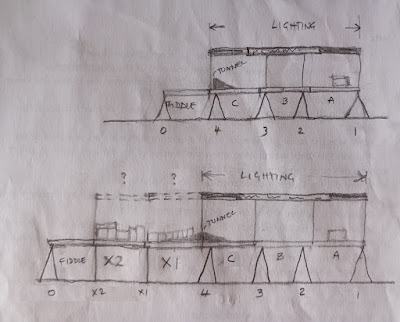
There are five existing trestles. 1-4 are used in the workshop, with the fiddleyard board end resting on the shelving unit. Trestle 0 comes to exhibitions as the stand-in. Trestles were positioned and numbered on the trestle and boards, for easy location.


The 2 new legs were positioned under the 2 new boards. Rather than just sit under the boards, wood blocks were glued on the legs and bolt fixing holes will be drilled next week. Some diagonal bracing might be needed after testing the bolt fixings.


The backscene was tackled next. The two existing panels were bolted in place and the new piece of MDF clamped in place (see below). 

We then discussed what the criteria were for reducing the top edge along the back: The existing station board has a lower edge in the area where an operator needs good vision and the ability to nudge a vehicle, if required. The same thing will be required on the new boards, so the whole of the new board panel and the high part of the existing backscene needed to be lowered.

Before

After a short trial, a reduction of 75mm was chosen. The new back panel was cut to size and the access holes to the 'hidden line' cut out.


The higher edge of the station panel was cut down to match.

After

The small end panel far left usually sits behind the bridge. There was an option to use this for both scenarios, but we decided that the arched hole for the bridge portal would need an infill piece to form a neater, square hole behind the pipework frame. We decided to make a new panel for the factory end.

There are other issues to be resolved. The current pelmet comprises copper pipe supports off the trestles up to a pelmet and a plastic gutter with LED lighting. We have yet to decide what to do over the extension. It would be much easier to keep the existing pelmet over the station boards and make an add-on lighting strip, on 1 or 2 new poles. Of course, the drapes on the front will need to be extended, but that has already been discussed with the fabricator, over breakfast.

This sketch took longer than expected to work out and draw the 4 and 6 board formats, so it is recorded here in case we forget what to do when setting the layout up somewhere!