Showing posts with label Magnets. Show all posts

Wednesday 5th March 2024

Worklist: Fit the three siding magnets.

The uncoupling magnets need to come up reasonably close to the underside of the track, so holes are required in the plywood base. The position of the magnets was carefully assessed to suit operations and avoid any framework underneath. 4 holes were drilled in the corners, then a small handsaw was used on the sides, before cleaning up using an electric file. 


The printed circuit board track is laid on thin cork, but as the Peco track sleepers are thicker than the printed circuit board track, it is laid directly on the plywood base. When everything was aligned, the Peco track was pinned down.


Thin card squares were slipped under the track where there were magnet holes. This will support the ballast which is laid later.

The completed new trackwork

The long siding has been given two uncouplers in case something needs to be left at the very end. Note: the Peco 0-16.5 Flexitrack sleepers were separated and moved to a more realistic spacing. 


Geoff is ordering more servos for the points and uncouplers and had purchased two of the 4-servo Merg controllers, which he will assemble in due course. Stephen had purchased more Slaters coursed stone plastic sheeting and will make a mock-up structure to extend the bridge over the new front board unit.

We were pleased to hear this week that Chris and Ted, who helped to operate Worton Court at the Birmingham NEC show in 2024, are available for the Aldershot show in October 11/12 2025. It will be great to have them on-board again.

Wednesday 1st May 2024

Worklist:
Fit new rainwater pipe.
Complete foliage around pipework (track leading to the fiddleyard).
Fit magnets to engine shed.
Add foliage to the long fence.
Add weeds to base of all buildings.
Assess the pallets and crates printed to date.

The third downpipe needed a double swan-neck, which Stephen fabricated from 4mm plastic tube. It took a fair bit of trial and error to get the joints correct, then a lot of filing to achieve the final shape. This was spliced onto 3+ lengths of 3D printed downpipe, and suitably weathered.


Main building cladding, windows and rainwater goods are all 3D printed.

Geoff continued to build-up the foliage on the pipework frame looping over the track going into the fiddleyard.


The engine shed is located over 4 vertical cocktail sticks, but is not fixed down, meaning it could fall off in transit. Rather than bolts, Stephen chose magnets - round magnets in a bucket (below) and rectangular magnets in a plasticard toolbox. Both were glued to the brick plinth with epoxy glue, 'diagonally opposed'. Countersunk holes were made in the plaster floor and 4mm screws inserted through to the plywood below. Both ends of the building were now perfectly held in place, but it can be removed for access to the lighting and the interior generally.


Geoff moved on to applying foliage to the long, bare Peco fence running up to the bridge. A variety of materials were used, starting with PVA, then a light spray of isopropyl alcohol diluted with water, which allowed to glue to spread more easily.


Both then moved on to applying small amounts of foliage along the bottom of the factory buildings and the cottages. Mostly subtle hints of weeds with occasional long grass clumps made from cut-down self-adhesive 'dots' of grass and a few electrostatic grass clumps.


Finally, an array of old 3D printed pallets was amassed, with many stacked and glued together to see how it might look. These were printed from drawings created 'in-house', but Geoff had also been experimenting with newly downloaded files, with varying success. Some of these included timbers which were far too thick to be used, often due to poor draughtsmanship. A selection of solid cases were also discovered which should make for an interesting yard. Geoff jokingly suggested that the front building could become a pallet/crate manufacturer. That's not a bad idea!


Stephen had made up one of the new flat wagons, but didn't have suitable wood for the decking and ends. Geoff had printed a few more wagons 'for homework' and supplied some of the basswood sheeting used on the prototype and the original stone wagons.


That water tower still needs a feed pipe!


The end of the layout
(so far....)


Wednesday 14th September 2022

Worklist:
Test uncouplers.
Start ballasting track.

Laurence still on family leave, so just two again this week.

This would be a full loco-powered test rather than a hand shunt exercise, so the layout needed to be set up for running. The first transition board (Quarry line tunnel mouth) would also be required for access to the engine shed siding.  Once set up, a loco, two wagons and a van were used to successfully test the magnets without any adjustment. The movement wasn't excessive, but it was more than enough to uncouple. The exercise did highlight the need for an overhaul of some couplers - one of those 'Roundtuit' projects.


It was then decided that ballasting the track was probably the next task - why not. Three tubs of different coloured ballast were retrieved from a storage box. The original Cottesmore trackwork was ballasted with a material used by British Airways to soak up oil spillages in their workshops (care of John). Cat litter had been tried, but (according to collective memory), it wasn't quite as good. The three tubs we had were different colours, possibly down to Stephen, who had experimented with colouring and blending ballast for a project. As the ballast would be dirtied/over-sprayed later, colour wasn't an issue. Size was, and we needed to sieve them first, but without a sieve, we improvised. Stephen's yoghurt pots to the rescue. A pot had holes drilled in the bottom for the maximum size required. Another with smaller holes - minimum size - and the 'fines' were also separated. It took some time, but the sound was pure Caribbean and we had quite a collection in the end.


Geoff mixed Screwfix PVA with water and filled a small applicator bottle. Instead of adding washing-up liquid to counteract surface tension, he now uses IPA Isopropyl alcohol, delivered via an atomiser. We started off with one tub of ballast, then sieved another tub and used that, and ended up using the third tub. The ballasting was completed on all three boards except for the tie-bar areas, which will be ballasted with care, in due course.

Dry ballast adjusted by brush.

IPA applied before diluted PVA.

A finger comes in handy as well.

Gaps left around tie bars where more careful application is required.


The photo below looks odd, but it's just those curved tracks tricking the eyes. This transition board will never be seen at an exhibition, as it will only be used in the workshop. The handed version (The second engine shed) will need ballasting as well, if we can scrape any together from somewhere!


Wednesday 7th September 2022

Worklist:
Continue wiring the uncoupling magnets.

Laurence still on family event/holiday.

Stephen had purchased some miniature SPDT toggle switches for the uncouplers and other 'accessories'. These needed to be sited and fitted onto the control panel. We were going to cut strips of coloured self-adhesive plastic to define the trackwork, but we didn't have any to hand. Some will be sourced. In the meantime, the track centres were lightly drawn in pencil, the switch locations agreed and marked, and fixing holes drilled. An old section of aluminium angle was adapted to take another switch, which was fitted inside the control panel. This will allow the switch directions to be reversed depending on whether the layout was in workshop or exhibition format. The only planned accessory so far is a set of operating doors which will be visible and not so dependant on switch direction.


The 4 uncoupling magnet toggle switches

The overall direction switch (reverses up/down)

The servos direction is determined by whether the signal wires are connected to ground. The doors can be added to this arrangement or labelled appropriately.
Then, testing of the magnet servos took place, but problems occurred. There was a lot of 'judder' in all of the servo's movements. Closer inspection showed that one of the known faulty servos had been installed by mistake and needed to be replaced. We then realised that the servos had been 'hard wired' together with crimped terminals. These had to be removed and new plugs with short wires soldered on the servo tails, to allow the servos to be swapped-out if required. It was also decided to add a socket for the doors servo. Geoff then connected the master 'trimming' unit and adjusted the end travel points.


This completed, testing progressed with a replacement servo, but things still weren't running smoothly. Geoff decided to fit a physical damper, to reduce the juddering. An ancient coil of phosphor bronze draught excluder provided short strips that were screwed near the moving end of the magnet holder and everything became much more stable.

Magnet up (against baseboard) 

Magnet down (away from the baseboard)

A strange day of obstacles and solutions, but progress was made. Now where can we get some sticky-back-plastic?


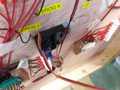
The servo controller board is becoming quite busy. It can handle 12 servos, but wiring them into the system requires more wires/connections and is generally more complicated than simple motor or solenoid actuators. The master 'trimming' unit connects to the orange RJ45 socket just off the left hand side of the photo. It needs practice and the instructions to carry out any modifications.


Thursday 31st August 2022

Worklist:
Continue with wiring the Masons board uncoupling magnets.

Laurence preparing for a family wedding, so just two this session, which ended a bit early due to other commitments.

After a quick review of what wiring was outstanding, Stephen asked Geoff for a wiring layout diagram to clarify exactly what was needed. It was more difficult than anticipated, but served as a useful exercise for both. With the diagram totally absorbed, a missing pair of wires (servo 5v & ground) were added between the control panel and the engine shed board. On the Masons board (below) the connector block was repositioned to keep the servo wires short enough to obviate extensions. The servos were then wired into the block. It was then possible to plug the test unit into the Servo Control Board on the engine shed board and operate both servos for the uncouplers. Progress.


A few more wires were added to both boards to complete the system. Good progress! 

The servo-powered units (points, uncouplers and any other accessories) require an on/off switch. Rotary switches are used for the points as these also indicate the route. For the magnets, Stephen had bought some miniature SPDT switches for the uncouplers and so a quick exercise was undertaken to confirm the position of the switches. These will throw up/down, but will require a master reversing switch to change between workshop and exhibitions where the control panel orientation is reversed! The additional 'accessory' is intended to be a door into the masons building/yard. There are 3 more channels available on the servo control board, but additional wires would need to be fitted into the loom to make use of them. They would have to be worth it!

Wednesday 24th August 2022

Worklist:
Progress fitting uncoupling magnets and loom wiring integration on boards.

A full house this week, although Laurence had brought along a Nigel Lawton Simplex kit he'd purchased a few years ago. He managed to spend the whole day reading the instructions and identifying the copious components in preparation for starting its assembly.

Stephen and Geoff coupled the Masons board to the Engine shed board which was already on trestles. The position of the magnets had been marked, but how to form the recesses in the plywood was the issue. Finally, 6mm holes were drilled across the recess area and then a burr fitted in a Dremel was used to cut away the remainder. Not the neatest job, but it worked without damaging the surface.


Stephen cleaned up the pair of 3D printed hinged holders and fitted their servos. Steel keepers were cut to size and hot-weld glued into position on the moving arm/frame. 2no. neodymium magnets were fitted to each keeper, and the units were screwed into place. The test controller was then connected to the first servo and it was successfully tested. 


Wagons being hand-shunted to test magnets are positioned correctly.

However, while fitting the second unit, a high pitch whine came from the first servo. Geoff knew immediately what it was. The test controller was still connected and, unlike the permanent controller, supplies power continuously to the stationary motor even when stationary. This causes the motor to overheat and the motor shaft melts the tiny gear freeing the motor run flat-out resulting in a burnt-out servo. Stephen replaced the servo with a spare and the unit was successfully fitted and tested.

The servos has certainly complicated the overall wiring and some time was spent rechecking that we had all of the required wires going to all of the boards/servos. The first check of the pin schedules indicated that 5v+- for the servos hadn't been included to the Masons board, but after physically testing connections, we eventually decided that everything was ok. Geoff is currently working on a comprehensive wiring diagram to make life easier - not before time!

Stephen's order of miniature toggle switches hadn't arrived in time, but fitting these into the control panel will be carried out in due course. 

Wednesday 10th August 2022

Worklist:
Continue additional wiring for servos.

Full house again.

Stephen had produced a freehand schematic diagram to clarify (in his mind) what was going on. It was loosely agreed by Geoff, but was then modified to include the new 12-way connector. 

Revised diagram


The 12-way socket was screwed into place and fully wired. Blue and white wires signify signal and activation uses. Some connect to the control panel and some to the Masons board.


The newly 3D printed cover was fitted and the wires tied in place.


Wiring continued, but progress was slow as wires went in all directions and constant pauses were required to keep on top of it all. A key issue is that all servos are controlled by wires between the main control panel and the servo control panel on the engine shed board. Wires to accessories on the Masons board are then routed onto the Masons board, using more connections through the loom. It was finally determined that sufficient wires between were in place to control two accessories on the engine shed board or 1 accessory on each of the boards. Enough for our immediate needs.


Beaten by a combination of the complex wiring and the heat, the meeting was adjourned.


Wednesday 13th July 2022

Worklist:
Start developing the drop-down uncoupling magnet mechanism.

Geoff had been under-the-weather last week and this week, Laurence was sensibly avoiding the extreme heat of the last few days.

Geoff assembled a variety of mechanism elements that he had developed for his 00 layout. These comprise 2no. 3D printed units - one for fixing to the layout and another to house the moveable plate for the neodymium magnet. He had produced numerous variations to suit different situations on the layout. Interestingly, some designs housed the servos on the base, but also had a few on the moving plate. Components for a basic type were selected. The units are designed for a single magnet with steel rod sections atop the flat rectangular magnets, to extend the downward-pull field required for Sprat and Winkle couplings. Our requirement now was for sideways attraction of the Kadee drop-bar provided by two side-by-side magnets. Some experimentation was required.

A rig was assembled to assess the required proximity of the magnet to the track - i.e. how big would the hole in the baseboard need to be? This confirmed a standard hinge was suitable and indicated the sort of packing required. After more experimentation, it appeared that the fields of the current stock of magnets varied from the originals, and a central spacer was now required to obtain maximum sideways throw. 


All components were glued onto a keeper plate and the assembly glued onto the hinge base plate. 


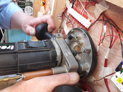
As no thought had been invested in allowing space to locate the magnet units (!), it was decided to fit the engine shed siding magnet first as it was the easiest to fit, requiring (almost) nothing to be moved. The position was marked underneath, a hole routed out (a dedicated ply spacer was made for the router) and the unit screwed in place. Lessons were learnt at every stage!


A plug-in servo tester/adjuster was used to test the installation, and proved it worked and was properly housed. A small square of foam was fixed on the baseboard to obviate 'slap' experienced on the 00 layout.


A bit of hand-shunting proved that we had a working uncoupling magnet. Finally, an assessment was made of the options and work required to move wires and connector strips for the other three units. One for next week.


Whilst dismantling the layout to fit the unit, the end of the 'Quarry tunnel' was visible. Apart from the vertical support on the corner, the tunnel is open at the back for access to track and stock.