Thursday 31st August 2022

Worklist:
Continue with wiring the Masons board uncoupling magnets.

Laurence preparing for a family wedding, so just two this session, which ended a bit early due to other commitments.

After a quick review of what wiring was outstanding, Stephen asked Geoff for a wiring layout diagram to clarify exactly what was needed. It was more difficult than anticipated, but served as a useful exercise for both. With the diagram totally absorbed, a missing pair of wires (servo 5v & ground) were added between the control panel and the engine shed board. On the Masons board (below) the connector block was repositioned to keep the servo wires short enough to obviate extensions. The servos were then wired into the block. It was then possible to plug the test unit into the Servo Control Board on the engine shed board and operate both servos for the uncouplers. Progress.


A few more wires were added to both boards to complete the system. Good progress! 

The servo-powered units (points, uncouplers and any other accessories) require an on/off switch. Rotary switches are used for the points as these also indicate the route. For the magnets, Stephen had bought some miniature SPDT switches for the uncouplers and so a quick exercise was undertaken to confirm the position of the switches. These will throw up/down, but will require a master reversing switch to change between workshop and exhibitions where the control panel orientation is reversed! The additional 'accessory' is intended to be a door into the masons building/yard. There are 3 more channels available on the servo control board, but additional wires would need to be fitted into the loom to make use of them. They would have to be worth it!

Wednesday 24th August 2022

Worklist:
Progress fitting uncoupling magnets and loom wiring integration on boards.

A full house this week, although Laurence had brought along a Nigel Lawton Simplex kit he'd purchased a few years ago. He managed to spend the whole day reading the instructions and identifying the copious components in preparation for starting its assembly.

Stephen and Geoff coupled the Masons board to the Engine shed board which was already on trestles. The position of the magnets had been marked, but how to form the recesses in the plywood was the issue. Finally, 6mm holes were drilled across the recess area and then a burr fitted in a Dremel was used to cut away the remainder. Not the neatest job, but it worked without damaging the surface.


Stephen cleaned up the pair of 3D printed hinged holders and fitted their servos. Steel keepers were cut to size and hot-weld glued into position on the moving arm/frame. 2no. neodymium magnets were fitted to each keeper, and the units were screwed into place. The test controller was then connected to the first servo and it was successfully tested. 


Wagons being hand-shunted to test magnets are positioned correctly.

However, while fitting the second unit, a high pitch whine came from the first servo. Geoff knew immediately what it was. The test controller was still connected and, unlike the permanent controller, supplies power continuously to the stationary motor even when stationary. This causes the motor to overheat and the motor shaft melts the tiny gear freeing the motor run flat-out resulting in a burnt-out servo. Stephen replaced the servo with a spare and the unit was successfully fitted and tested.

The servos has certainly complicated the overall wiring and some time was spent rechecking that we had all of the required wires going to all of the boards/servos. The first check of the pin schedules indicated that 5v+- for the servos hadn't been included to the Masons board, but after physically testing connections, we eventually decided that everything was ok. Geoff is currently working on a comprehensive wiring diagram to make life easier - not before time!

Stephen's order of miniature toggle switches hadn't arrived in time, but fitting these into the control panel will be carried out in due course. 

Wednesday 17th August 2022

Worklist:
Whatever it was supposed to be soon went out of the window!

No Laurence this week. 

Before they could get started on anything, Stephen and Geoff discussed the state of the wiring inside the control panel and how it was making wire-paths difficult to trace. Geoff floated the idea of rewiring the box - or at least the mess in the bottom of the box - and Stephen readily agreed. Geoff also floated the idea of replacing the soldered brass pins with two rows of standard connector blocks, and of using boot lace ferrules on the wires to connect them together. It didn't need any discussion - work started. And work continued until it was finished.

The connector strips were fitted into the spaces either side of the central plywood and brass pin 'connector strip'. Slowly, the wires were transferred over (and careful records taken).


 What a transformation.


A typical set with ferrules and the amazing square crimper.


Wednesday 10th August 2022

Worklist:
Continue additional wiring for servos.

Full house again.

Stephen had produced a freehand schematic diagram to clarify (in his mind) what was going on. It was loosely agreed by Geoff, but was then modified to include the new 12-way connector. 

Revised diagram


The 12-way socket was screwed into place and fully wired. Blue and white wires signify signal and activation uses. Some connect to the control panel and some to the Masons board.


The newly 3D printed cover was fitted and the wires tied in place.


Wiring continued, but progress was slow as wires went in all directions and constant pauses were required to keep on top of it all. A key issue is that all servos are controlled by wires between the main control panel and the servo control panel on the engine shed board. Wires to accessories on the Masons board are then routed onto the Masons board, using more connections through the loom. It was finally determined that sufficient wires between were in place to control two accessories on the engine shed board or 1 accessory on each of the boards. Enough for our immediate needs.


Beaten by a combination of the complex wiring and the heat, the meeting was adjourned.


Wednesday 3rd August 2022

Worklist:
Progress fitting of new loom socket and associated rewiring.

A full house today and some explaining required to bring Laurence up to speed on the loom modifications to accommodate the servo operated magnets.

The 20-way socket and associated connector block were moved to make way for the new 12-way socket (Green one in the middle) and a new 12-way connector block fitted below it to terminate connections. Some of the 3-core servo cables may need to be extended to ease congestion. Some of the new wires to this socket will come from the control panel to operate the 4 new uncouplers and future servo operated features/accessories on the two boards. The latter includes an opening door and possibly a simple crane. Others wires will connect those servos to the Servo Controller Board (SCB) on the engine shed board. There is capacity for more items, if required.


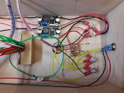
Until now, there was only a 12v DC supply provided to these boards, which directly fed the SCB. However, all other boards on Worton Court had a 19v DC supply for ALL accessories and lighting. The first job was the removal of the dedicated 12v voltage regulator in the control panel (the bottom of the two units seen below) to feed 19v to the new boards. The second job was the fitting of a dedicated voltage regulator next to the SCB set to 12v. 


Returning to the boards, wires for the new magnet servos were fitted between the socket and connector block. As well as 3 on-board wires from the SCB to each servo, signal wires are required from the control panel to the SCB to activate the servos. Furthermore, the servos on the Masons boards require signal wires from the control panel to the SCB and then operating wires through the loom to the Masons board. Using servos certainly increases the complexity of the wiring! 


Diagram of MegaPoints Servo Controller wiring example:


The servo's are 'trimmed' using a small plug-in (remote) device.


Geoff had redesigned the servo mount to include oval fixing holes to allow for alignment adjustment and to accommodate a 'small protrusion' on the servo casing that made the unit unstable. All resolved now.


Another session that resulted in some aching heads, but progress is being made.