Thursday 27th August

Worklist:
Point actuators.

Again, we reviewed Geoff's work on the revised 'all-in-one' actuator and agreed that it was the right solution. That said, we turned into a production line again and modified the rest of the units.

Laurence drilled the additional holes for the new horn. We decided on a hole on each side, just in case we wanted to switch the position. He also fitted the extra micro-switches required to change the polarity of the frogs.

Geoff turned up spacers to lift the new horns off the base plates. His prototype has a rod spacer, but this proved difficult to tighten, so the new ones were made of hex bar. The turned top fitted into the base of the horn.


Stephen made up the wire connectors, trimmed the horns and performed the final assembly.

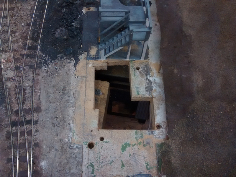
Once the first one was ready, Geoff fitted it alongside his first unit, but this time wired the frog switch as well. The fitting became a group-effort as we developed a method of aligning and fixing it in place. The hole in the baseboard needed to be countersunk slightly to give better clearance for the horn-end, but generally, fitting was simple, as the actuator wire could be easily 'tweaked'.

We were so engrossed with our tasks, that we overran lunchtime by 40 minutes!

As reported previously, Geoff had tested the new unit on a DC supply and finding it no different to half-wave AC, had purchased a low voltage DC supply. We now went over the options for operating the actuators. The existing solenoids had stud contacts on the panel (i.e. two supply wires in the loom) and a common return from each board. Most points were operated singly, so the same two loom wires could be used to feed the output from a DPDT switch, with a cross-over. Where two points were currently controlled together, Geoff suggested we operate them in sequence, like a real railway. This would either require additional wires from the extra switches, or a cunning plan to stagger them operating. G&S both agreed that the latter would be a great challenge to design, with the ability to fall back on the extra wire option if we failed. Watch this space!

With the old studs being replaced with rotary switches (our first choice and what we had a lot of!), we looked to the control panel itself. We always knew it would have to be replaced at some time, as the layout requirements were likely to change. Stephen had donated an old panel, which will need a new top, but was otherwise quite suitable.

The old panel had two power supplies. An AC supply for the ECM speed controller and a DC supply for the points. The latter was needed as the capacitor charging load would have interfered with the loco control. After some tests on the new servo motors, Geoff declared that this would no longer be a problem, so a single AC supply would suffice. As Geoff had already fitted a bridge rectifier for the feed to the DC power supply, only one, large AC supply was now required.


Thursday 20th August

Worklist:
Point actuators

The first thing to do was examine the mechanism Geoff had made after our last meeting (see last post), and it was wonderful.


One change from the previous version was the change to a DC power supply. A small, adjustable transformer (eBay) now provides a low voltage supply through a DPDT rotary switch. Another change was the micro-switch for the frog, which had been moved onto the end of the tie-bar unit, on a temporary base extension, to allow for easier adjustment.

Convinced it was the way to go, Stephen and Geoff set about converting the other 8 units to the new design. This entailed taking everything off, drilling a new hole for each switch (they pivoted around one of the existing holes), assemble switches and resolder wires. We also took the opportunity of replacing the plastic spacers for the servo mounts for wider, wooden spacers that were more stable. Laurence prepared the rectangular plastic sections for the tie-bar units and the plastic tube reinforcement for the actuator wire.


After lunch, another tie-bar unit was fabricated and, together with one of the motor units, fitted in place of an existing point motor. However, it wasn't easy to fit and adjust the two units and the connecting wire, which would require some serious thought to overcome satisfactorily. We could also see that due to the size of the new unit, the adjacent motors would be difficult to fit and could require additional cranks and fittings - not what we wanted for reliable operation. Spirits deflated, we decided to review the situation at the next meeting.


Driving home, Stephen started to consider reverting to the original direct-wire design, but using the excellent large-sweep servo action. Over a cuppa, the idea turned into a sketch, which was sent to Geoff, who immediately saw the potential and started to investigate. The following day, he had a working mechanism - mk 3 (or is it mk4?).

Stephen's design didn't work, as elements clashed or moved excessively, but Geoff's solution with an off-centre tie-bar horn/wire not only created a solid, easy to build unit, but was also much more flexible to fit.

The unit being tested.

The unit installed on the layout.


We are back in business!


Homework 15th August

Following the session on 13th August, Geoff couldn't resist having a go at modifying an actuator along the lines we'd discussed as we were finishing for the day.

To summarise - The MERG design we were following constrained the servo arm movement to just that required to move the point tie-bar - approximately 2mm. A bit deflated with the units performance, Geoff described how a 'mainline' actuator swung through an arc of about 160 degrees. The resulting horizontal arm movement was not uniform, but slower at both ends. Light bulbs flashed and we wondered if we couldn't do something similar. We could easily reposition the micro-switches and use a single-ended servo 'horn'/arm.

His new arrangement had no loop to take up the slack, just a curve in the connecting wire. The servo swung nicely and closed the switches positively, with no stress - it was wonderful!


Note how the connecting wire is positioned in the very bottom hole on the servo arm, creating maximum 'thrust'.


Sorted!


(Geoff apologises for not turning the radio off)


Thursday 13th August

Worklist:
Point actuators

Yes, the whole session was spent trying to sort out the point actuator design. Geoff had manufactured all of the remaining units which saved some time. However, he reported that on testing, they all operated in slightly different ways, which did not bode well for setting them all up to be consistent.

We started to investigate separating the servo unit from the tie-bar mechanism. Stephen had used the method on one of his layouts and had linked the two units with wire, which had a connector for adjustment and an omega loop. We found an old actuator unit of sliding plastic tubes. We remember making it, but not what it was for (might even be on this blog somewhere!). Laurence drilled a hole in the end of length of 8BA studding and Geoff soldered-in a short piece of spring wire. The assembly was secured into the plastic tube unit, and the unit screwed over the tie-bar. The servo unit was fixed a short way from the actuator and spring wire, with a simple loop (not Omega this time), connected between them.

The usual DC supply was employed, but there was a problem with the servo arm bouncing off the micro-switches. We also found that the linkages generated too much slack and that the servo would occasionally stall, requiring a finger poke. It was all very dispiriting, and clunking solenoid motors seemed like a good option.


Around this point, we also discussed how we were going to adapt the existing control panel & wiring to the new units. We could use DPDT switches to deliver a fwd/rev DC supply as had been made the previous week. Geoff had also proposed using an AC supply through a SPDT switch with diodes on each output to recreate the fwd/rev supplies. To cheer us up, we decided to try this out and a switch unit was assembled. We tried different voltages to overcome the drop the diodes created and soon found we had a very smoothly working servo - just what we'd been looking for.


However, (lots of 'howevers' this week!) we still had to sort out all of the problems we'd encountered - a tall order. Right at the end of the session, as we were about to pack up, Geoff described how 'mainline' point actuators travelled far more than our model. In fact instead of a couple of degrees, they swung through approximately 160 degrees. This had the effect of varying the speed of the operating arm, which slowed at the ends. Could something like this solve our bounce-problem? It might be worth looking into next time.


Thursday 7th August

Worklist:
Point actuators
Actuator installation assessment and testing

With Laurence being 'lasered' again, Geoff took over the mantle of actuator manufacture and the remainder of the base plates were drilled, ready for assembly.


In parallel, Stephen started to assess how the actuators would be fitted, as a combination of the existing point design and H&M actuator 'flexibility' had resulted in some awkward positions to be overcome. However, the first to be changed was on the new board, on a new point and no obstructions. A length of spring wire was bent to fit onto the actuator horn and the unit screwed into place. NB: Ordinary holes in the base plates might need to be elongated to allow for adjustment. However, in this instance, alignment was OK. 


On the 6mm baseboard, it was quite noisy. The servo was stripped down and grease applied to the gears, which made some improvement. The other locations were on 1/2" chipboard, which might dull the sound further.

Testing with a railway controller threw up some issues with over-voltage and, it was suspected, the back EMF. A standard, adjustable power supply was fitted, and running at 3 volts, it was much better. Introducing a 10 ohm resistor worked a little better still. Some actuators will be operated in pairs, so different resistances can be applied to suit the positions.

All forward/reverse testing was with 4-hands swapping loose wires, so a simple reverse  switch and power socket was made up to make it easier.


A useful and satisfactory start to the replacement procedure.


Thursday 30th July

Worklist:
Point actuators
Gas engine motorisation
Perimeter wall

Laurence continued with point actuator number two - only 7 more to go!

Having completed the engine and made the components for the motor-drive, the unit was assembled. It ran quite well, except for a judder that was put-down to the nylon rod on the electric motor being eccentric. A new one was made using a pencil rubber centre-drilled in the lathe. The new unit worked much better. A wooden block and brass spring allowed it to be mounted under the floor panel and successfully tested in place.


Mounting the updated floor required a hole in the baseboard...


Walls - Geoff had previously glued some paper mache over a board joint and it hadn't fully dried out, so the layout couldn't be turned around. Stephen took the opportunity of progressing with the perimeter walls to the manor house grounds, on the new board.

At the Epsom & Ewell show, we came across a single sheet of English Garden Wall bond plastic sheet. It was the only one there and had 5 stretcher courses instead of the more common 3 (see example below)


The plastic was cut to size and glued onto the plywood walls with contact adhesive. Thin plywood was then cut for the brick piers - two laminated units for the main gateway and several for mid-wall piers. These will be covered in plastic sheet and applied to the main wall.


Space was at a premium this week, so Stephen ended up using the band-saw on the floor.