Wednesday 28th November

Worklist:
Point rodding.
Cassettes.

A straight follow-on from last week. Laurence pressed on with the extra cassettes while Geoff and Stephen progressed the point rodding.

Stephen started by testing the stock clearance of the rodding along the workshop. Ideally, it could be a little further away from the rails, which would coincide with the ideal route through the timber walkway. First, a sloping panel was removed from the existing walkway and a new, flat panel inserted. The end rodding support was lifted and re-glued so the rods were aligned nicely past the new panel. Planks were then inserted beyond the rodding, completing the extended path.


Geoff researched 'stacked' cranks and produced a unit with three cranks, at different levels, for the far side. Approaching the frame, the three rods split, so a two crank unit was made for the final turn into the frame. A single crank was already to-hand for the single rod. Once complete, the position of the crank bases was determined, the grass removed down to baseboard level and the cranks glued down.

Loose rodding to determine the correct crank positions


Geoff had determined that properly cleaned piano wire could be soldered, which meant we comfortably had enough rodding material. Stephen took three short lengths of brass and assembled them in two support frames - only one would be required, but the other kept the ends in place temporarily. With the ends flattened and tinned, the rods were soldered onto the cranks. After applying a slight curve, the loose ends were soldered together and, once the temporary support was cut away, the end was glued down between the path planks. Two small squares of plasticard representing steel plates bridge the rodding gap.


The final flourish was a panel of floor planking for the frame working area. It's just below the platform level, which looks about right. Its extent can be adjusted when we look at the area in detail.


The question of where the bell, light switches and track layout board are to be located was raised again. Geoff still favours a high-level pelmet over the lever handles with the track board position 'to be agreed'. Stephen favours the side handrail with a box and a sign at a lower level, as previously suggested. Geoff will investigate prototypes further, and report back.


Wednesday 21st November

Worklist:
Point rodding and fittings.
Extra cassettes.

It was straight to work this week as everyone knew what to do. While Geoff and Stephen returned to their particular point rodding tasks, Laurence restarted his cassette production line.


Stephen sieved some of the standard ballast to get some finer material, which was then sprinkled over dilute PVA painted into the clear slots between the three sleeper routes. Whilst that was drying, he assembled the three-rod unit feeding the two points at the tunnel end of the layout. The rod ends were flattened and tinned ready for soldering to the cranks. The furthest crank had been glued down previously and it now had its rod soldered to it. The other two loose crank units were soldered to their rods and the whole assembly adjusted for the best alignment. Card packers were used to lift the crank bases to the required height and both were glued down with weights on top, to secure their positions. The rodding supports were adjusted and packed to describe a slight curve and they they too were glued down and weighted.


Meanwhile, Geoff finished off the rodding for the two points adjacent the frame. Due to the need to reserve space for the distant pointwork, small cranks were generally used. (The gap for the remote rodding can be seen on the left).


Stephen cleared the excess ballast from under the rails. Rods were bent to shape and the ends flattened and soldered onto the cranks.


Finally, Geoff and Stephen then completed the rodding for the last remaining point. We weren't entirely sure how to deal with the small angle in the tie-bar rod, but the single swinging-arm seemed the most appropriate, as the real-life travel would be very small.


We still have the triple-rod assembly to extend from the board joint to the lever frame. The rodding at the board edge will be secured under a new timber step along the pathway and run down to the gap already created. At this point, three cranks need to be fitted in close proximity, but we have already found photos of this being achieved with curved-end cranks, which are available on our brass sprue. It's then a short run to the frame. After our initial concerns, the disruption to the layout has been far less than anticipated. Once we've completed the making-good to the ballast and foliage, and painting the new equipment, we hope it will all virtually disappear, to be found by eagle eyes only.

Those levers still need painting!


Wednesday 14th November

Worklist:
Review Stephen's trial signalling system.
Continue installing rodding and pointwork controls.
Cassettes.

A full house, and all had been impressed with the layouts at the Tolworth model railway show over the weekend. As usual, Stephen and Geoff had taken the opportunity to look at how exhibitors had displayed their layouts, with particular reference to lighting, pelmets, backdrops, stock storage and the like. It will all go into the mental tumbler when we get a bit closer to our exhibition. There were also a few items that took our eye. Point operation using servos like ours, running very smoothly on MERG control units. There was also a layout with signal/light panels, albeit modern outline, similar to our current investigations which obviously inspired Stephen....

First-up this week was Stephen demonstrating a switch panel he'd made up to control the bell and three LED lights that make up the 'active' part of our new signalling system. After working through circuits using IR detectors, multiple relays etc, he'd settled on a simple twin rotary-switch affair - one for each signal, but both activating the bell and lever frame light. Although the unit met with a less than enthusiastic reception, the comments were actually quite 'overcomable' and inspired a deeper discussion on what we actually wanted to happen. It might just find its way onto the layout in due course.


The switch panel mock-up, with one 3-position rotary switch per approaching train. This would be housed under the scenery on the bridge board.  Operation - Train stops at sign, appropriate switch thrown to 'Frame' to ring bell and light LED. Pause. Throw switch to Sign to cancel bell and frame light and light sign LED. Train moves off and switch/light cancelled.


A modern sign found on the web showing a signal light housing (top of pole) and some appropriate wording. And the trial sign with the elements 'aged' to suit our period better. Time will tell what the final design will be, but we did agree that something with working lights will appear in due course.


While Laurence went back to his extra cassettes, Stephen and Geoff returned to pointwork and rodding installation. A brief discussion about rodding and ballast conflicts below trackwork showed that much larger excavations were required - wider and deeper. Stephen set about digging out the ballast full sleeper-to-sleeper width and also removing the trackbed (old vinyl floor sheeting) to get down to baseboard level. This will allow a layer of sieved ballast to be laid at a low enough level for the rodding to be installed over it, and under the rails. 


He then returned to the main 3-rod strip alongside the workshop. Three lengths of brass rod were fed into the supports, spaced at 10ft centres. We had decided that a slight curve in this rodding would be practical and appropriate for the location. The end crank base is already glued down, so the other two will be soldered to the rodding first, so that the bases could all be glued level.


Geoff concentrated on the two points adjacent to the lever frame. The closest was easiest as most of the cranks will be under a new floor panel. The other just requires two cranks for completion. Three down - one to go!


The final discussion was on the framework required for the bell, light and switching, and possibly a track diagram too, for the lever frame. Above the levers looked too high, so the next most obvious was across the right-hand side of the working platform. This would also form a barrier to walking off the side of the platform. Something similar had been seen at the Tolworth show - a small ground frame with an equipment box on one side and a barrier on the other. We could combine both on the right-hand side of the frame (above).


Another feature that could be adopted was extra cassette storage. This was provided by vertical boxes that attached to the back and side of the fiddleyard. Like the operator on the layout, a long step might be required for Laurence to reach the higher level items, if we decided to use them too.


Wednesday 7th November

Worklist:
Review Geoff's new ground frame.
Start point rodding installation.
Build new cassettes.

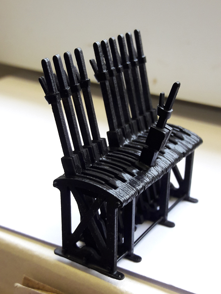
A full house and attention was focused on the ground frame Geoff had made since the previous week, announced by a set of photo's he'd circulated. The frame was based on one at the LT museum and discussions with staff who had knowledge of general frames and their operation. In particular, the juxtaposition of pivot and rodding connections on the levers on ground frames and signal boxes, which certainly clarified the situation. A new design was drawn-up and components laser-cut from 2mm Pressphan, a compressed paper/board with high temperature tolerance used as an electrical insulator in many products.


The completed frame includes a 'spare' lever and a shorter frame locking lever. The black sealing coat will be augmented with rust and dirt, together with the levers being correctly coloured for their uses.


Some leftover components comprising frames, levers, packers, washers etc. (Top right there are some impressive 2mm dia rings with holes, that are perfectly sound. A testament to the laser and Pressphan board.)


Stephen and Geoff moved on to fitting rodding and crank parts onto the layout. First, a quick check was carried out on Stephen's drawing, to ensure that every point is in its 'normal' position, when the corresponding lever and lock lever is in the back position. (Normal meaning Cottesmore trains straight to platform and quarry trains to siding track). A couple were found to be wrong, which just required one crank to be reversed on each run. Geoff decided to fit the ground frame and glued two sleepers to the underside. Its position was then assessed for stock clearances and general work-ability, before being glued down. There are a couple of vertical crank frames on the sprue that we'll never use, but they looked ideal for mounting the locking unit. Extra 'sleepers' were added and the cranks fitted - an adjustable for the point operator and two small ones for the lock. Brass rod was squeezed in the vice and filed to form a clevis before being soldered to the cranks. For the lock itself, the 'left over plastic kit box' was raided, and some suitable trapezium shaped sprues were found. It was all very fiddly work, but it did look good when completed.


Stephen had continued to work at the quarry end of the layout and cleared the copious ballast from the crank positions. Short pieces of leftover basswood were cut into sleepers and the crank base and crank secured with a fine track pin, cut and filed to length. Superglue held everything in place. A few more were made to save time later.


The furthest point did not have a lock, which was ideal as a starter. The next two units served the mainline point - actuator and then lock. A route through the ballast leading to the point tie-bar was cleared and another unit was glued. Due to the angle, this will need a 'special' crank - TBA. Leaving the next section of ballast in place, the location of the lock crank base was cleared. The rodding route will be cleared next week.


The final photo-shoot proved that we had made the right decision to fit the frame and rodding system. The working floor area will be raised to platform level and widened, which will require adjustment of the steps. Chequer plate seems to be the finish most used.


The frame and pelmet for bell, light and switches will be fitted in due course, but this last view is exactly what we'd envisaged, with the controller 'orchestrating' the arrival of trains from Cottesmore and the quarry.


It will virtually all disappear in rust, grime and foliage, although there was a suggestion that we don't age it too much, if at all, as it could be that it's a new installation. We'll have to put it to the committee!

While all this was going on, Laurence had started making four extra standard length cassette units. Apart from cutting the aluminium angle to length, all other components had already been prepared as a batch, when the earlier units were made.


Wednesday 31st October

Worklist:
Review point crank purchase.
Review rodding support assemblies.
Research rodding, crank and lever frame designs.

There had been a works outing to the ExpoNG show at Swanley over the weekend and we were all impressed with the standard of modelling. We had previously discussed the items we needed for our layout and were able to purchase a sheet of 7mm etched brass cranks from Roxey Mouldings. These had 3D detail which looked very good. We also purchased 4 x 500mm lengths of 0.81mm brass rod, 'just in case' we decided the piano wire was too difficult to use for the rodding.

We also kept our eyes open for other features that might prove useful and were soon surprised to find that we all agreed on how good one particular backscene was. It turned out that 'Shipmeadow Workhouse' (009) used a proprietary sheet that just contained an all-cloud sky. Unfortunately, the owner couldn't remember the make, so some investigation is required. He had also added a small amount of printed building detail at road level, which is probably what we will do as well, albeit ours will be rural scenery.


Back to business - a few of the cranks and their bases were liberated from the sheet and placed on the layout. We were all pleased with the effect. (Brass rod with flattened end - see later)


Stephen displayed a number of 2 and 3-rod support units he'd made up from the cardboard components laser-cut the previous week. Piano wire made the units come to life.


Stephen's provisional drawing of the crank and rodding for the layout was examined and the pro's and con's of 90deg or 45deg rod to crank alignment discussed. We decided that neither was 'correct', accepting that both had their benefits in different situations. Looking at the design in detail, we determined the lever frame layout and rodding egress was critical. We specifically needed the overall frame width (lever width and spacing x 9 etc.) to ensure it fitted on the end of the platform. Furthermore, the height of the operating floor in relation to the station platform needed to be established (height of rodding, extent of lever below floor level etc.). Geoff decided to research the lever frame in more detail using Google image search. He was soon joined by Stephen and Laurence, keen to unravel the enigma of facing locks, frames, cranks (everything actually!). After prolonged research, we decided on a small locking unit fitted beside the track (plasticard block, scale size approx 5 x 7 mm). With regard to the frame, a few 'simple' prototypes were located and, after measuring Geoff 'miming' operating a lever frame, and recording key dims, a simple frame design was drawn-up. The idea was to laser-cut several 1mm card frames (two patterns required) that could be laminated together in a block and fitted with scratchbuilt levers. We started with the design on the left, but it seemed too narrow/light-weight and finally agreed the other. We'll run-off the working pieces next week, and put a frame together to see if it looks OK. A rail and backboard will also be required to mount the bell and light switches.


Meanwhile, Stephen and Laurence returned to the cranks. The crank detail is beautiful so a fine, but robust joint with the rodding was required. While Laurence worked on using tiny pieces of pared-down square tube with flattened ends, Stephen tried flattening the end of the brass rod in the vice and filing to a rectangle. Whilst the square tube was good, the flattened rod-end method was very acceptable and far, far quicker. Stephen then removed the old point levers from the five points affected. The sleeper extensions will be left in place, as a reminder of the system development.


Detailed planning of the lever frame area followed. We decided the working floor could be at platform level and still allow the rodding to emerge at ground level satisfactorily. Rodding for the two points 'north' of the frame could be accommodated albeit with some of the gear being 'hidden' under the floor (with a removable panel for maintenance, of course). Whilst not necessarily the final design, we were happy that the frame and working area worked OK.


There's a lot to do and we are still wary of the amount of 'destructive' work required to fit everything, but it's a challenge we look forward to.