Just Geoff and Stephen this week.
Geoff had redesigned the magnet frame from the previous week and 3D printed 3 in the black PLA. The black produces a much cleaner model, but is harder to inspect, especially in shadowy spaces. One unit was assembled for installation on the engine shed board.
Firstly, space had to be made for the unit as they weren't part of the design when the electrics were first installed. Fortunately, the connector block and loom plug base could be moved down without too much bother. Geoff had undertaken some research on neodymium magnets and discovered that they are produced with (at least) two field configurations. However, ours seem to be the same pattern, so the new unit was fitted. Some alignment adjustments were required to get the best coupler operation, but a working position was achieved. On his 00 layout, Geoff had designed and 3D printed a drilling jig that fitted between the rails and allowed accurate alignment holes to be drilled. He might make one for the two remaining magnets - because he can!
We then moved onto the Masons yard board. First, a connector block was moved from the right hand side, through a pre-prepared hole in the cross-brace and onto to left hand side.
The central brace was then found to be exactly where the magnet needed to go, so after marking the spot, a plunge saw was used to cut the brace. However, the brace fixing screw was also exactly in the magnet position. This time, brute force was used to wrench the screw out.
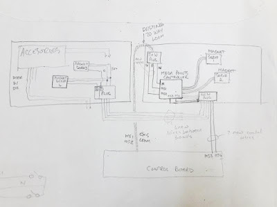
The existing wiring was then reviewed. The introduction of the servo-driven magnets required additional wires; A) To connect them to the Mega Point Controller (MPC) on the engine shed board and B) to connect to on/off switches on the control panel. The two new magnets on the engine shed could use spare loom wires, but we now needed to connect the two new uncouplers from the Masons board to the MPC as well.
Configurations of signal wires, switch wires, common ground wires were assessed. The Cinch plug and sockets we had available also had to be taken into account. All of the notes and diagrams from the initial board wiring records were also reviewed. The future use/operation of the spare 'ports' on the MPC (operating doors, cranes etc.) also had to be considered. After considerable deliberation, a plan was decided. A new 12-way socket would be fitted to the engine shed board. All existing and new servo control wires would be wired through this socket, which would free-up connections to the shed board (see later*). There was plenty of spare wiring capacity on the Masons board for the new wiring.
The session was ended at this point as we were both ready for a break!
* The redesign process above also highlighted the 'apparent' lack of consideration of lighting control. On the other boards, a laptop power supply provided 19v DC to each board which was then used for lighting, sound units, accessories etc. The switches for these were located at the back of the layout. However, for the two new boards, there wasn't a single 'back', as they would be reversed in 'Shed' and 'Exhibition' format. Switching could be provided on (under) the boards or on the control panel. The extra wiring capacity makes both options viable. It should also be remembered that in these operational configurations, the control panel needs to be reversed, so 'up/down' switches have to be considered. The current plan is to have a master switch reversing the operations for each arrangement!


