Showing posts with label Point motors. Show all posts

Wednesday 27th March 2024

Worklist:
Make and fit diagonal bracing for the new board legs.
Make and fit end panels for transporting new boards in one unit.
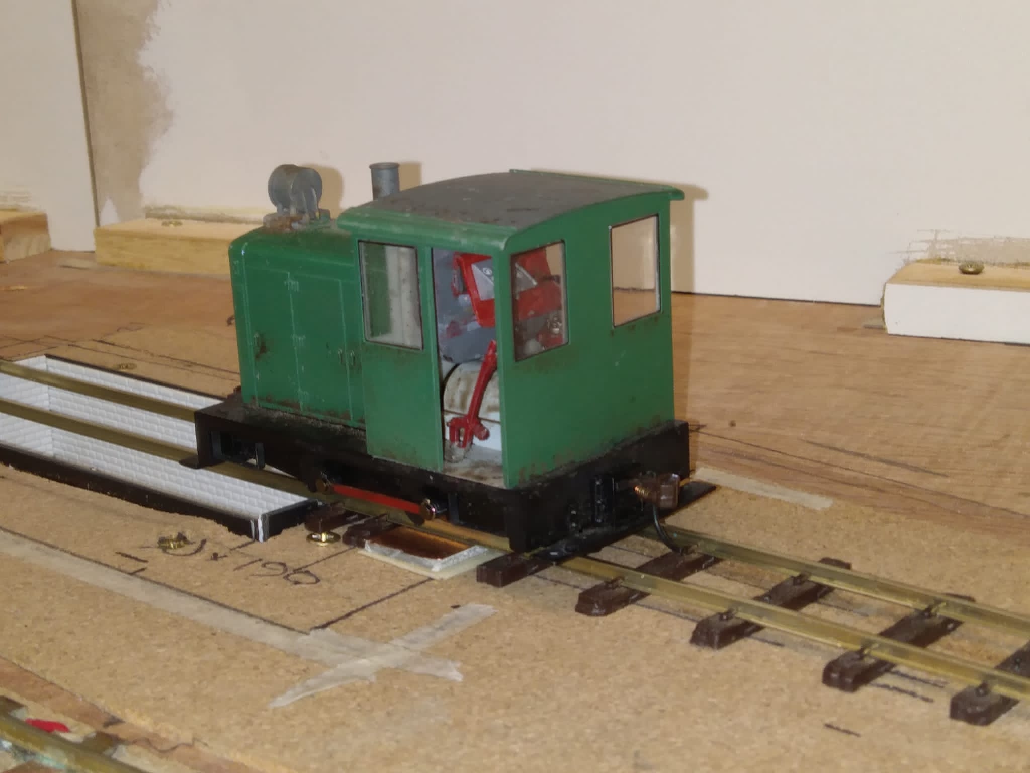
Fix faulty point outside engine shed.
Wire-up power supply for engine shed lights.


Having made the two leg frames for the new boards, it was decided that adding diagonal bracing would turn them into a rigid frame that was safer and more useful. Two lengths of timber were cut to length and bolts holes drilled at the ends. Self-tapping M6 sockets were fitted in pre-drilled holes in the uprights and the cross-braces fitted. However, these braces were fitted with one on each side, which did not provide the rigidity assumed. The last job of the day was to modify one of the braces so that they could be fitted beside each other, with a bolt in the centre, to make it rigid.


A fault had been noted in the operation of the point from the engine shed into the ash siding. The boards were clamped vertically on the frame for easy access to the underside.


After much investigation, Geoff determined the travel of the servo horn was excessive, causing 'bounce-back'. The only solution was to reprogram the point motor on the master servo control module. Instructions had to be re-read and the handheld programmer tracked down, but the issue was resolved, eventually. (Good practice for the exhibition!).


After unbolting and placing the two new boards on the floor, a compact and comfortable overlapping arrangement was established. 


The ends, bolt hole and pin positions were measured, before two pieces of MDF were cut to size and holes drilled. The ends were then bolted in place and a very neat transportable module was revealed.


Meanwhile, Stephen was able to wire-up the shed lights to the power supply unit installed many months previously, which provided a much better view of the interior.


The lamp shades were cut from a strip of pill holding plastic.


Wednesday 10th August 2022

Worklist:
Continue additional wiring for servos.

Full house again.

Stephen had produced a freehand schematic diagram to clarify (in his mind) what was going on. It was loosely agreed by Geoff, but was then modified to include the new 12-way connector. 

Revised diagram


The 12-way socket was screwed into place and fully wired. Blue and white wires signify signal and activation uses. Some connect to the control panel and some to the Masons board.


The newly 3D printed cover was fitted and the wires tied in place.


Wiring continued, but progress was slow as wires went in all directions and constant pauses were required to keep on top of it all. A key issue is that all servos are controlled by wires between the main control panel and the servo control panel on the engine shed board. Wires to accessories on the Masons board are then routed onto the Masons board, using more connections through the loom. It was finally determined that sufficient wires between were in place to control two accessories on the engine shed board or 1 accessory on each of the boards. Enough for our immediate needs.


Beaten by a combination of the complex wiring and the heat, the meeting was adjourned.


Wednesday 8th December 2021

Worklist:
Refit engine shed point servo, point actuator and section wiring.

Just Laurence and Geoff as Stephen not too well, but there was no slacking. The layout was cleared of loose items and the boards clamped vertically to give easy access underneath. The realignment of the engine shed road meant moving the point and so refitting the servo meant a new hole for the activation wire. Once complete, the point, new track section and the inspection pit rails were all satisfactorily tested.


Thursday 12th November

Worklist:
DC feature power to the baseboards.

Laurence on another lunchtime jaunt, so just two this week.

To run DC power to the boards for lighting, motors, sound(?), we could either run a separate supply to one board and have jumpers across the two joins or add it to the loom. The latter was neater, but the central ('platform') board had no spare pins. We decided to add a separate 2-pin plug on this board.

We have a DC and an AC supply to the control panel. The AC supply for the speed controller was originally used for the point relays and servos as well, after running through a bridge rectifier. However, we discovered that the frog micro switches on the point actuators created a momentary short-circuit which interfered with the loco speed. We subsequently added a 19v DC supply (laptop) to power the electromagnetic uncoupler, and this supply could be used for the point power.

First job - move the feeds to the point actuators to the DC supply. At the same time, a pair was taken to two spare pins on the loom wiring strip, off the same supply.

Pre rewiring layout. Blue/brown AC feed.
Instead of running three new pairs from the control box, a single pair was taken down to the first junction in the loom and then three pairs joined with crimped connectors. The DC supplies (black/red) were run out of the board sockets to a 2-way connector. From here, supplies can be run to individual voltage regulators, for each 'feature'.

'Bridge' board
'Yard' board
 The 'Platform board pair ran to a floating, female socket, with a male plug mounted on the board, running to the 2-way connector. Not very pretty, but it prevents accidental short circuits of the 19vac 3amp supply. We'll keep our eyes open for a neater plug/socket.

'Platform' board
 The final layout. The bridge rectifier has been left in place, as it doesn't have to be removed.


Thursday 8th October

Worklist:
Control panel

We were eager to get the panel finished this week and got straight down to work (after our first cup of tea).

After a brief logistical discussion on how to lay out the relay and power supply units, Geoff and Laurence made-up a strip of plywood to form a sub-assembly. Meanwhile, Stephen made up all of the connecting wires together with the 18v ac supply 'posts' taken from the old control panel.  A bridge rectifier was added to convert the supply to dc. The power units (which can take anything up to 30v) were trimmed to 1.5v and 5v. All of the units were assembled on the strip, the panel dropped into place. Geoff then made all of the final connections and we carried out an initial test.

Geoff in his element
The final assembly

Two of the relay boards
Power components
The 18v ac supply enters the box on the right and terminates on two bolts. One pair goes to the bridge rectifier that feeds to two point power supplies - one unit set to 1.5v for the point (servo) motors and the other (set to 5v) for the relays.

We connected the first layout board, to test the system, and it worked, much to Laurence's delight. It only has point, but it was very pleasing:


Laurence 'tickled pink' that it was working!
The other two boards followed, but it was found that a few of the points needed rewiring on the boards as, in their old configuration, points were wired and operated together, whereas the new system was one-switch-per-point. Furthermore, not all of the switches were correctly aligned, but a note was taken of all the anomalies and Geoff swapped the wiring later. One of the relays was also found to be faulty and will require replacement.

We were so pleased to complete the system overhaul, that we intend to have a running session next week, to give everything a good work-out, remind us what have achieved to date and where we are going.


'Our man' removing the hinge from the old panel.


Thursday 24th September

Worklist:
Point actuator
New control panel

Just two this week, as Laurence had a car failure and spent the morning with a very nice man from the AA.

Stephen removed the first actuator we had fitted (with the separate slider-unit), modified it with the extra operating arm and refitted it. Point actuators were finished! Hopefully.

Geoff started to strip out the wiring from the temporary control panel. A print of the old panel layout allowed the wire numbers to be recorded. The ringed point, formed part of the engine shed cross-over, was the only one that needed extra wires.

The ringed point needed two wires not available from the solenoid wiring scheme.

Careful labelling and recording of each removed wire.

Quite a birds nest.

We were also keen to find out if there would be sufficient wires in the existing loom for the new actuators. These would require two wires per servo (polarity reversal by DPDT switch). The old system had one wire to each of two coils on the H&M motors and a single, common return. However, a few of the points were operated together, requiring only one wire to two points. In the end, we were lucky, and only the engine shed point needed two extra wires (circled above). We were able to use the point motor common return as one, but a new wire would have to be fitted into the loom. A quick check revealed that there was one spare pin in the connectors.

Geoff then raised the question of ancillary items such as lighting, the gas engine motor and probably others. Whist the end boards had spare wiring capacity, the middle board was now full. We could gain two wires (enough to provide auxiliary power to the board) if the two crossover points above, used just two wires. However, this would create a unique situation on the new control panel - one switch to operate two points. Furthermore, both would move at the same time, something Geoff had been very keen to avoid, as a signal man would operate each in turn. There were three options:

a) Use a single switch to control two points simultaneously and accept the operational 'anomaly'.

b) Use separate switches (one extra wire required). Lighting etc. would require a different solution.

c) Use a single switch, but design a system to delay the second point moving until the first had stopped.

The latter really put the cat among the pigeons! Both S&G recognised the potential of the challenge and the final part of the day saw the temperature in the workshop rise as two brains struggled with the problem. On parting, both resolved to solve it!


Stephen initially sought a wire/component solution, but then started investigating electronic delay modules and circuits. It looked promising, but then Geoff came up with a wire/diode only solution. Exquisitely fiendish!
Part of the proof that it worked!

This gave us three working solutions, but which one we adopt will depend on how important saving wires in the loom is. The meeting next week should be interesting!


Thursday 17th September

Worklist:

Point actuators.

It was 'full steam ahead' this week, with all three of us fitting actuators to both of the main boards. Most needed wires extended, but not the same blade remedials as last week.


After testing, the actuator wires were trimmed to the correct length.

Just one to go. The first actuator we fitted was of the original design, which would have to be replaced in due course.

A brief discussion took place regarding the switching system we'd agreed to use on the new control panel. Many of the components had arrived, but the relays were still winging their way from China.

We confirmed that the relays would be operated by their own 5v supply, switching the 1.5v (min.) supply feeding the servo's. It was acknowledged that as the servo's appeared to operate differently, it might be necessary to increase the base supply voltage and fit local resistors to the more freely-operating units.

The original system had pairs of stud contacts feeding each of the two coils on the H&M point motors, with a common return. The two feed wires are reused for the servo supplies, with the polarity reversed by the relays. A DPDT switch would do the job much simply, but we couldn't find a suitable rotary switch.
Stephen would make a start on the veroboard bases, fitting dil sockets, wires and terminals, allowing the relays to be dropped in later.

Thursday 10th September

Worklist:
Point actuators

Yes, business as usual..... but we are making progress.

Geoff and Stephen fitted the operating wires to the remaining actuators. We discovered we'd bought two thicknesses of spring/piano wire, so decided to try both out.


Meanwhile, Laurence stripped out some existing H&M units and started to fit the new ones. Things didn't go as smoothly as they could have. The assemblies worked, but alignment of the operating wire needed to be more precise. We accepted that we were still developing a method of assembly and soon corrected the issues - a useful exercise.


Stephen fitted another unit and transferred the wiring from old to new units. As found previously, short wire extensions were required.


The other problem that came back to haunt us was John's method of point making. He preferred not to split the blades from the frog rails, which increased the stress on the blade/tie bar joints and obviated copper-clad tie bars. To overcome this, he silver soldered a solid tie bar to the blades. To prevent a short circuit, the tie bars could not come into contact with the stock rails. The old H&M rotating arm held the tie bar down in place, but this would not be retained. The first point to be converted needed something else to hold the tie bar down, and a short section of rail, laid down the centre of the track, was used.


As we are prone to do, we veered off on another, but allied subject. How were we going to operate the points? We were using toggle switches for the sections, so a rotary switch made sense. We had several 'standard' switches, but these only clicked through a small angle where something larger would be preferable. Stephen had sourced a switch, but found it only available as a DPST option (two on-off circuits instead of DPDT where polarity change-over could be achieved). Geoff suddenly remembered that he had TWO stashes of the switches, which were 'played with' and admired. Stephen suggested using them in conjunction with relays, to achieve the change-over. This arrangement was approved. It was agreed that instead of a round knob/pointer, something more demonstrative could be made up.


Thursday 27th August

Worklist:
Point actuators.

Again, we reviewed Geoff's work on the revised 'all-in-one' actuator and agreed that it was the right solution. That said, we turned into a production line again and modified the rest of the units.

Laurence drilled the additional holes for the new horn. We decided on a hole on each side, just in case we wanted to switch the position. He also fitted the extra micro-switches required to change the polarity of the frogs.

Geoff turned up spacers to lift the new horns off the base plates. His prototype has a rod spacer, but this proved difficult to tighten, so the new ones were made of hex bar. The turned top fitted into the base of the horn.


Stephen made up the wire connectors, trimmed the horns and performed the final assembly.

Once the first one was ready, Geoff fitted it alongside his first unit, but this time wired the frog switch as well. The fitting became a group-effort as we developed a method of aligning and fixing it in place. The hole in the baseboard needed to be countersunk slightly to give better clearance for the horn-end, but generally, fitting was simple, as the actuator wire could be easily 'tweaked'.

We were so engrossed with our tasks, that we overran lunchtime by 40 minutes!

As reported previously, Geoff had tested the new unit on a DC supply and finding it no different to half-wave AC, had purchased a low voltage DC supply. We now went over the options for operating the actuators. The existing solenoids had stud contacts on the panel (i.e. two supply wires in the loom) and a common return from each board. Most points were operated singly, so the same two loom wires could be used to feed the output from a DPDT switch, with a cross-over. Where two points were currently controlled together, Geoff suggested we operate them in sequence, like a real railway. This would either require additional wires from the extra switches, or a cunning plan to stagger them operating. G&S both agreed that the latter would be a great challenge to design, with the ability to fall back on the extra wire option if we failed. Watch this space!

With the old studs being replaced with rotary switches (our first choice and what we had a lot of!), we looked to the control panel itself. We always knew it would have to be replaced at some time, as the layout requirements were likely to change. Stephen had donated an old panel, which will need a new top, but was otherwise quite suitable.

The old panel had two power supplies. An AC supply for the ECM speed controller and a DC supply for the points. The latter was needed as the capacitor charging load would have interfered with the loco control. After some tests on the new servo motors, Geoff declared that this would no longer be a problem, so a single AC supply would suffice. As Geoff had already fitted a bridge rectifier for the feed to the DC power supply, only one, large AC supply was now required.


Thursday 20th August

Worklist:
Point actuators

The first thing to do was examine the mechanism Geoff had made after our last meeting (see last post), and it was wonderful.


One change from the previous version was the change to a DC power supply. A small, adjustable transformer (eBay) now provides a low voltage supply through a DPDT rotary switch. Another change was the micro-switch for the frog, which had been moved onto the end of the tie-bar unit, on a temporary base extension, to allow for easier adjustment.

Convinced it was the way to go, Stephen and Geoff set about converting the other 8 units to the new design. This entailed taking everything off, drilling a new hole for each switch (they pivoted around one of the existing holes), assemble switches and resolder wires. We also took the opportunity of replacing the plastic spacers for the servo mounts for wider, wooden spacers that were more stable. Laurence prepared the rectangular plastic sections for the tie-bar units and the plastic tube reinforcement for the actuator wire.


After lunch, another tie-bar unit was fabricated and, together with one of the motor units, fitted in place of an existing point motor. However, it wasn't easy to fit and adjust the two units and the connecting wire, which would require some serious thought to overcome satisfactorily. We could also see that due to the size of the new unit, the adjacent motors would be difficult to fit and could require additional cranks and fittings - not what we wanted for reliable operation. Spirits deflated, we decided to review the situation at the next meeting.


Driving home, Stephen started to consider reverting to the original direct-wire design, but using the excellent large-sweep servo action. Over a cuppa, the idea turned into a sketch, which was sent to Geoff, who immediately saw the potential and started to investigate. The following day, he had a working mechanism - mk 3 (or is it mk4?).

Stephen's design didn't work, as elements clashed or moved excessively, but Geoff's solution with an off-centre tie-bar horn/wire not only created a solid, easy to build unit, but was also much more flexible to fit.

The unit being tested.

The unit installed on the layout.


We are back in business!