Review point crank purchase.
Review rodding support assemblies.
Research rodding, crank and lever frame designs.
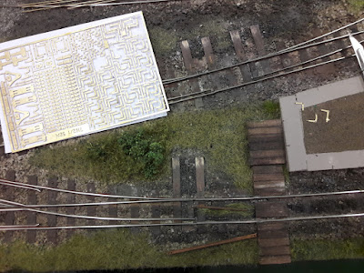
There had been a works outing to the ExpoNG show at Swanley over the weekend and we were all impressed with the standard of modelling. We had previously discussed the items we needed for our layout and were able to purchase a sheet of 7mm etched brass cranks from Roxey Mouldings. These had 3D detail which looked very good. We also purchased 4 x 500mm lengths of 0.81mm brass rod, 'just in case' we decided the piano wire was too difficult to use for the rodding.
We also kept our eyes open for other features that might prove useful and were soon surprised to find that we all agreed on how good one particular backscene was. It turned out that 'Shipmeadow Workhouse' (009) used a proprietary sheet that just contained an all-cloud sky. Unfortunately, the owner couldn't remember the make, so some investigation is required. He had also added a small amount of printed building detail at road level, which is probably what we will do as well, albeit ours will be rural scenery.
Back to business - a few of the cranks and their bases were liberated from the sheet and placed on the layout. We were all pleased with the effect. (Brass rod with flattened end - see later)
Stephen displayed a number of 2 and 3-rod support units he'd made up from the cardboard components laser-cut the previous week. Piano wire made the units come to life.
Stephen's provisional drawing of the crank and rodding for the layout was examined and the pro's and con's of 90deg or 45deg rod to crank alignment discussed. We decided that neither was 'correct', accepting that both had their benefits in different situations. Looking at the design in detail, we determined the lever frame layout and rodding egress was critical. We specifically needed the overall frame width (lever width and spacing x 9 etc.) to ensure it fitted on the end of the platform. Furthermore, the height of the operating floor in relation to the station platform needed to be established (height of rodding, extent of lever below floor level etc.). Geoff decided to research the lever frame in more detail using Google image search. He was soon joined by Stephen and Laurence, keen to unravel the enigma of facing locks, frames, cranks (everything actually!). After prolonged research, we decided on a small locking unit fitted beside the track (plasticard block, scale size approx 5 x 7 mm). With regard to the frame, a few 'simple' prototypes were located and, after measuring Geoff 'miming' operating a lever frame, and recording key dims, a simple frame design was drawn-up. The idea was to laser-cut several 1mm card frames (two patterns required) that could be laminated together in a block and fitted with scratchbuilt levers. We started with the design on the left, but it seemed too narrow/light-weight and finally agreed the other. We'll run-off the working pieces next week, and put a frame together to see if it looks OK. A rail and backboard will also be required to mount the bell and light switches.
Meanwhile, Stephen and Laurence returned to the cranks. The crank detail is beautiful so a fine, but robust joint with the rodding was required. While Laurence worked on using tiny pieces of pared-down square tube with flattened ends, Stephen tried flattening the end of the brass rod in the vice and filing to a rectangle. Whilst the square tube was good, the flattened rod-end method was very acceptable and far, far quicker. Stephen then removed the old point levers from the five points affected. The sleeper extensions will be left in place, as a reminder of the system development.
Detailed planning of the lever frame area followed. We decided the working floor could be at platform level and still allow the rodding to emerge at ground level satisfactorily. Rodding for the two points 'north' of the frame could be accommodated albeit with some of the gear being 'hidden' under the floor (with a removable panel for maintenance, of course). Whilst not necessarily the final design, we were happy that the frame and working area worked OK.
There's a lot to do and we are still wary of the amount of 'destructive' work required to fit everything, but it's a challenge we look forward to.


