Review Stephen's trial signalling system.
Continue installing rodding and pointwork controls.
Cassettes.
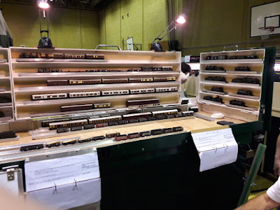
A full house, and all had been impressed with the layouts at the Tolworth model railway show over the weekend. As usual, Stephen and Geoff had taken the opportunity to look at how exhibitors had displayed their layouts, with particular reference to lighting, pelmets, backdrops, stock storage and the like. It will all go into the mental tumbler when we get a bit closer to our exhibition. There were also a few items that took our eye. Point operation using servos like ours, running very smoothly on MERG control units. There was also a layout with signal/light panels, albeit modern outline, similar to our current investigations which obviously inspired Stephen....
First-up this week was Stephen demonstrating a switch panel he'd made up to control the bell and three LED lights that make up the 'active' part of our new signalling system. After working through circuits using IR detectors, multiple relays etc, he'd settled on a simple twin rotary-switch affair - one for each signal, but both activating the bell and lever frame light. Although the unit met with a less than enthusiastic reception, the comments were actually quite 'overcomable' and inspired a deeper discussion on what we actually wanted to happen. It might just find its way onto the layout in due course.
The switch panel mock-up, with one 3-position rotary switch per approaching train. This would be housed under the scenery on the bridge board. Operation - Train stops at sign, appropriate switch thrown to 'Frame' to ring bell and light LED. Pause. Throw switch to Sign to cancel bell and frame light and light sign LED. Train moves off and switch/light cancelled.
A modern sign found on the web showing a signal light housing (top of pole) and some appropriate wording. And the trial sign with the elements 'aged' to suit our period better. Time will tell what the final design will be, but we did agree that something with working lights will appear in due course.
While Laurence went back to his extra cassettes, Stephen and Geoff returned to pointwork and rodding installation. A brief discussion about rodding and ballast conflicts below trackwork showed that much larger excavations were required - wider and deeper. Stephen set about digging out the ballast full sleeper-to-sleeper width and also removing the trackbed (old vinyl floor sheeting) to get down to baseboard level. This will allow a layer of sieved ballast to be laid at a low enough level for the rodding to be installed over it, and under the rails.
Geoff concentrated on the two points adjacent to the lever frame. The closest was easiest as most of the cranks will be under a new floor panel. The other just requires two cranks for completion. Three down - one to go!
The final discussion was on the framework required for the bell, light and switching, and possibly a track diagram too, for the lever frame. Above the levers looked too high, so the next most obvious was across the right-hand side of the working platform. This would also form a barrier to walking off the side of the platform. Something similar had been seen at the Tolworth show - a small ground frame with an equipment box on one side and a barrier on the other. We could combine both on the right-hand side of the frame (above).
Another feature that could be adopted was extra cassette storage. This was provided by vertical boxes that attached to the back and side of the fiddleyard. Like the operator on the layout, a long step might be required for Laurence to reach the higher level items, if we decided to use them too.


