Wednesday 23rd October 2024

Worklist:
Fully test the new section control arrangement.
Rectify intermittent point adjacent quarry signal.
Modify control panel sections to new configuration.
A few more weeds to the station area.
Bits and pieces of maintenance.

The full layout was set up and a loco run through all areas to test the new system. All switches and sections worked as required - a great relief. With so many section overlaps and switches, the ease of use was a key question, but again everything appeared to work quite rationally.
 
At the end of the last session, the point adjacent the quarry signal was playing-up. Instead of a lengthy investigation, a wire was loose on the point switch in the control panel - job done!

Geoff moved on the 'downgrade' the station area. He regularly says that it is far neater than preserved railways he's worked on, so out came the PVA, a suitable old brush and bags of scatter material.


Stephen amassed some old rolls of electrical and gaffer tape, and updated the control panel sections to suit the new layout. Note the two signals.


The mainline track sections and switches (top) have been in existence for many years, but the wiring has been modified to make better use of them. Together with the new orange section, trains controlled from the mason yard can now pull right up to the signals.


Signals 'action' panel on the left and the completed section controls on the right.

Recap: When a train approaches a signals and stops, the operator selects Frame on the appropriate 'action' panel and the bell on the ground frame rings and the light flashes, alerting the station controller. Once the track is clear, the 'action' switch is turned to Sign, whereupon the light on the signal flashes to advise that the train can move into the station. 

Wednesday 16th October 2024

Worklist:
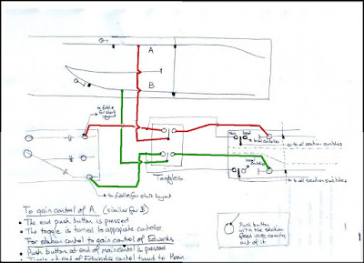
Work through the 'design' of the new wiring scheme for selection of controller for the two sections approaching the signals and carry out the conversion. 

This will allow a 'remote' operator to drive trains from the storage area/yard/quarry right through to the signals. (If the main station operator is busy, trains were often left on adjacent sections for the main controller to drive when free, but they can get forgotten!).

Geoff had produced a schematic layout of the proposed rewiring:


The two boards were clamped together vertically on trestles. The red section that had already been converted, was tackled first and existing wires were traced under the boards and through the looms. The first problem was that the existing wiring did not follow the normal system for a track feed i.e. one common feed and one section feed from the control panel. The end section feed was looped from the adjacent track which meant a change-over could not be created. The wiring was corrected and tested.

Green section: Due to the way the point frog for the siding was constructed (John's standard method) a new section had to be created from it, to the tunnel, to prevent a short circuit. An extra toggle switch was required on the mini panel, which was fitted. The new wiring was installed and tested.


Finally, the boards were laid flat and trains successfully run through all scenarios. The exercise has corrected many issues (known and unknown) and will enable us to run more authentic trains into the station, from both destinations. The small panel isn't very attractive, but space is restricted, so it will have to remain for the time being.

Wednesday 9th October 2024

Current format: Trains coming from the quarry, under the control of the Edwards board controller, can be run right up to the signal, whereupon, the correct signalling process (bell/flashing light sequence) can be carried out. During the recent 'trainees running session', Ted, who seemed to like the process, asked if the same routine could be applied to the mainline as well? Although Geoff and Stephen thought it could, they couldn't answer categorically and so agreed to investigate.

Worklist: Investigate the above!

The mainline track is already separated from the adjacent, station section, but is electrically bonded to the section. However, the yard control panel has an additional, switchable section for 'something' in the area, but is it on the station board or the Edwards yard board? There is an identical section for the quarry line, but no apparent rail break on either track/board.

Basically, the rest of the session was spent tracing wires. Then, when an initial plan evolved, an extra wire was inserted in the loom, and track feeds and switches were adapted, but without achieving the desired arrangement. A lot more investigative work is required!

Where Geoff spent a lot of the day...


Wednesday 2nd October 2024

Worklist:
Repair point (engine shed to siding).
Add electrical jumper to Edwards yard point off mainline.
Glue scrap timber pile together.
Add a sleeper to the end of the siding.


The engine shed to siding point had 'played-up' the previous week by not travelling the full way and bouncing back slightly. Close examination determined that the wire actuator needed to throw further, but once moved to the next servo arm hole, the wire was too short and a new wire was required. Once fitted, Geoff needed to reprogram the point using the MERG programmer.

One of the point blades on the point into Edwards Yard was receiving an intermittent electrical feed. This is normally fed through the pin at the pivot pivot at the end, but they sometimes lose the contact with the printed circuit-board sleepers. The standard solution is to solder a jumper wire under the point, from the stock rail to the blade, which worked again.

In between assisting with the above, Stephen  glued the pieces of scrap timber he'd created previously.


Stephen got the brown paint out and touched up several sections of rail where the 'rust' had worn off. While painting the rail at the end of the shed siding, he queried the lack of a buffer and Geoff knocked-up a prestigious bolted-down sleeper.