Wednesday 24th July

Tasks:
Continue to develop the new boards design.

Back to full strength today, but Laurence had to be brought up to speed on developments last week as his laptop is in for repair.

The shorter of Geoff's new designs relied on 21" radius curves as opposed to the standard 30" we employ. On their own they are not an issue, but as part of a 'reverse curve' (or 'S' curve) they could be a problem with long overhanging stock and so testing was required. A sheet of ply was marked out with the curves and a length of 0-16.5 flexitrack fixed in place. Stock with potential problems were identified: a 0-6-0 loco with a long rear overhang and a long Kadee coupling, a coach with the coupling on the body and long overhang, and a light wagon with a long coupling. These were coupled-up on the track and run back and forth. The Kadees were at their sideways limit, but they worked ok. They would not be able to couple on these curves, but the exercise showed that derailment was unlikely.


We then examined Geoff's designs in detail and, after extensive discussions, decided to merge the two.

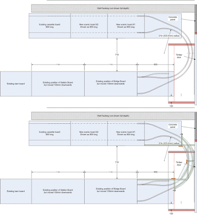
The transition boards will be 800mm long, which means the reverse curves will be reduced in severity. The boards will be rectangular and solid-topped to allow for some scenery, for use in the workshop setup only. This being the case, Geoff finally accepted the idea of including an engine shed just beyond the bridge, even though there would be an extensive loco facility on the first new exhibition board on the back wall.

Two new 800mm long exhibition boards would be located before the fiddleyard, along the racking wall. These boards would be supported on simple timber frames attached to the racking. Geoff had also developed the earlier 'split-board' scheme into a very nice area.


One concern was that in the workshop, the hidden quarry line would be against the racking and would not be readily accessible, but access holes on the board tops might be incorporated or items moved off the racking to retrieve derailed stock.

We then spent some time discussing board construction and methods of securing boards together. The last board we made used 2 layers of 9mm ply for the framing and a 9mm top, which we were very happy with and will replicate. Good quality ply is required and a new source needs to be found, but first, a cutting schedule will be produced to determine the amount of ply required.

The curved end boards will comprise plywood tops on minimal timber frames/supports. Standard flexitrack would be used on non-scenic boards and handmade (code 100 FB rail on PCB sleepers) elsewhere. Bolts and homemade location pins had been used for the existing boards, but Geoff had used some proprietary locators and toggle clamps on a school layout, which we will also investigate.




Wednesday 17th July

Tasks:
Develop the new board design.

With Laurence on grandparent duty this week, it fell to Stephen and Geoff to continue developing the new baseboard design.

Previously, we had agreed that an extra 800mm scenic board could be accommodated by moving the fiddleyard into the garage (2). A track and building layout was achieved, but on subsequent consideration, there were minor reservations. Stephen wasn't entirely happy about the track and building arrangement - it was a bit tight. A standard board (1134mm) could be accommodated by moving the layout to leave the minimum space around the end (3). However, this had implications regarding the control panel clashing with the lathe. G&S were also concerned that in mid-winter, the garage was not a place to spend any appreciable time and so another plan developed. Keep the fiddleyard in the workshop but rotated and placed against the racking, then create connecting tracks via the garage. During the measured survey, a concrete panel was located that dictated part of the track route, but the space and structures were drawn up and a design achieved which allowed a longer new scenic board (4).

The overall design seemed feasible, but detailed trackwork design showed it was a bit too tight - the standard track position at one end needed a tweak, which produced an interesting solution. Trackwork on two smaller boards was designed so that when bolted together for exhibitions had standard end connections, but when split, incorporated the tweak mid-board (5). We now had a decent layout design, but the connecting tracks and boards looked a bit OTT.

Geoff slept on the problem overnight and next morning, came back with a new solution. Move the fiddleyard and the new board(s) to the racking side and form the connecting tracks within the workshop (6). Geoff produced detailed layouts, for consideration.

The design sequence:

The 'through-the-wall' scheme and the ingenious split board solution (4):
The engine shed is well located for access to/from the station area and the industrial unit has good access to the fiddleyard. It had good scenic possibilities with a quarry (flooded?) in the foreground.


The transition boards can be scenically treated for added modelling scope and workshop running sessions.

The longer transition boards look good, but we'll mull it all over again next week!


Wednesday 10th July

Tasks:
Develop the new board design.

In Stephens absence the previous week, Laurence and Geoff had suffered minor misgivings about 'hacking into' the heart of our lovely layout and started to investigate an alternative option. Stephen had pursued the centre-insert 'idea' and produced a few sketches along the lines of the sketch below.
Just to let the original idea run its natural course, the foamboard sheet was reinserted and the scheme worked-up to scale and with more accurate trackwork. The option chosen included a reverse siding into the stone cutting building to enable wagon exchange, but there simply wasn't enough space to create a feasible shunting area. The central insert was suitably abandoned!

Geoff then explained that a new board between the bridge and fiddleyard board had been investigated and looked much more promising. Firstly, however, a board length of 800mm had been chosen (rather than the initial 650mm). This was to create a 'pair' of scenic boards that could be assembled together for transportation - perfect. The downside - it wouldn't fit in the workshop. A hole in the lightweight partition between the workshop and garage was proposed, and the fiddleyard relocated into the garage(?!).

Moving on swiftly, the sketches for the new board were explained. The first consideration was whether it was necessary to maintain the same connections for the mainline to the fiddleyard from the new board. If an extra connection was created on the fiddleyard edge, a different exit for the mainline could be accommodated. (Different connections would be used for the different length layouts). This agreed, space was available for an engine shed and an industrial unit - possibly timber but probably stone based. The tunnel link to the fiddleyard would be under a hill extension, but the industrial unit could also form part of the enclosing structure.

Several new variations were now considered and sketched up. However, thoughts soon turned to wagon exchange. Ideally, this would be placed at the back of the layout for easy reach. A straight into the fiddleyard (with another cassette connection) couldn't be ruled out, but the pointwork could be difficult. It was then suggested that the siding route into the building was pointing to the rear of the tunnel line and a sector plate suddenly occurred to us. This was developed for a while with more than tacit approval. 


By now, we were all mentally exhausted, but we had a new plan to develop further, next week.